
Imaging method and device using shearing waves

Inactive Publication Date: 2004-08-03
SOC DELASTOGRAPHIE IMPULSIONNELLE POUR LES SYST DE MESURE DE LELASTICITE SEISME
View PDF9 Cites 125 Cited by
  • Summary
  • Abstract
  • Description
  • Claims
  • Application Information

AI Technical Summary

Benefits of technology

said motion parameter is the strain of the viscoelastic medium: this arrangement is particularly useful in the last case envisaged hereinabove, since it makes it possible to dispense with the displacement of the bank of transducers, which displacement would otherwise disturb the measurement of the displacement of the points of the observation field;

Problems solved by technology

This technique has the drawback of allowing the analysis of just a single point of the viscoelastic medium under study each time a shear wave is generated.
If one wishes to obtain a complete image of the observed viscoelastic medium, it is necessary to repeat the operation a very large number of times, this involving a considerable idle time (for example, several minutes) to obtain this image.
This considerable idle time renders this prior art method impractical to use.
Moreover, such an idle time may impede the use of said method to obtain an image of a living tissue, which is always in motion.

Method used


Image

  • Imaging method and device using shearing waves
  • Imaging method and device using shearing waves
  • Imaging method and device using shearing waves

Examples


Embodiment Construction

In the various figures, the same references designate identical or similar elements.

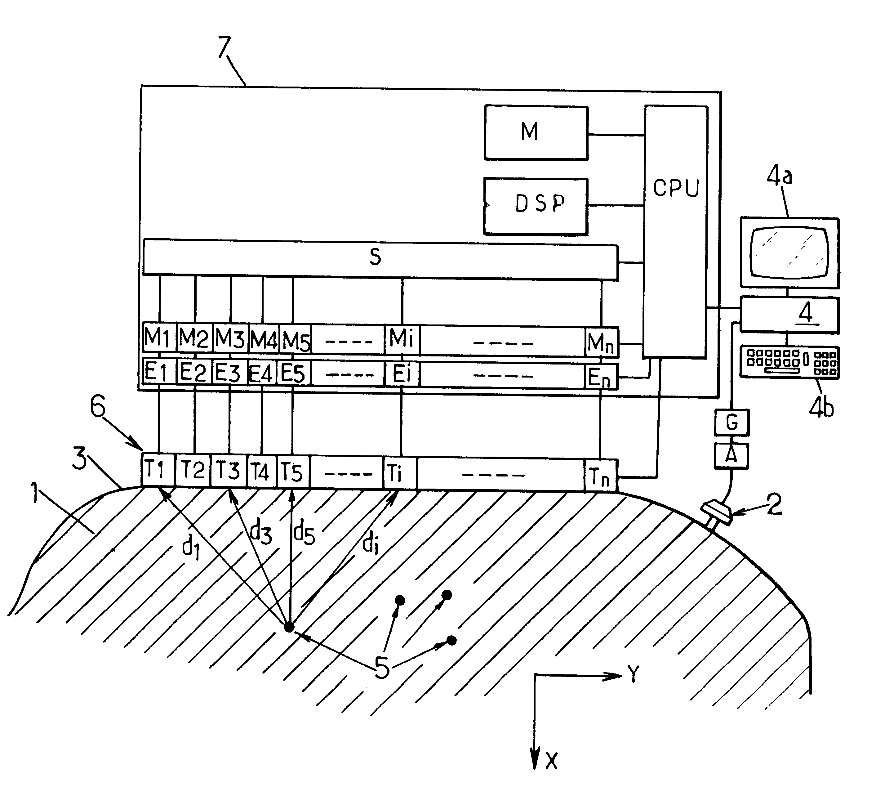
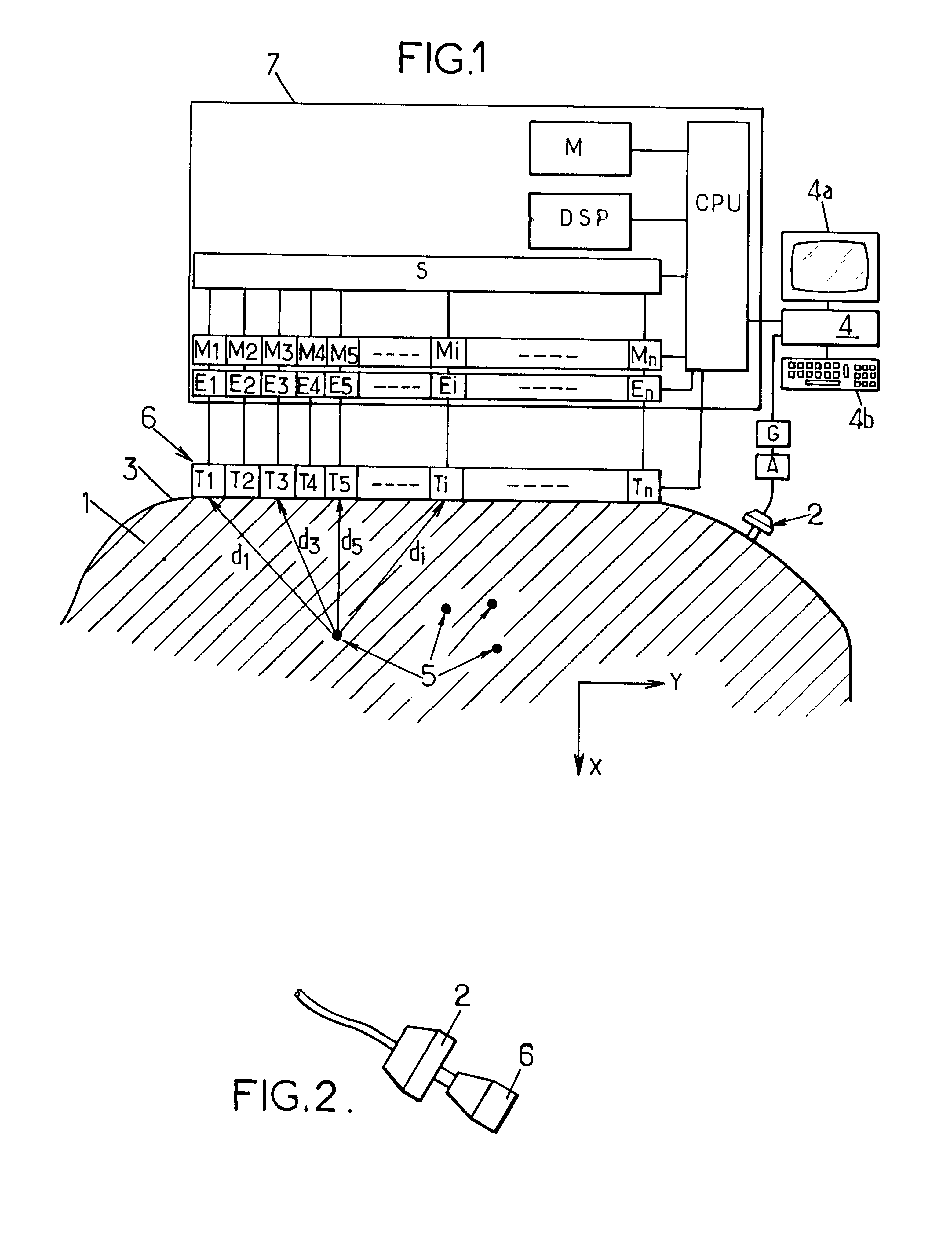
FIG. 1 represents an example of a device for imaging by shear waves according to the invention, for studying the propagation of elastic shear waves in a viscoelastic medium 1 which is diffusing with regard to ultrasonic compression waves, and which may for example be:

an inert body, in particular in the case of quality control for industrial applications, in particular agro-food applications,

or a living body, for example a part of the body of a patient, in the case of medical applications.

This device comprises an acoustic transducer such as a loudspeaker 2 or a vibrator can which is arranged against the outside surface 3 of the observed medium 1, this surface 3 consisting for example of the skin of the patient in medical applications.

The loudspeaker 2 can be controlled by a microcomputer 4, for example by way of a low-frequency pulse generator circuit G (this circuit can consist in particular of the s...


PUM


Abstract

The invention concerns an image method for observing the propagation of low-frequency shearing pulse wave simultaneously in multiple points of a diffusing viscoelastic medium. The method consists in transmitting at a very high rate ultrasonic compression waves enabling to obtain a succession of images of the medium; then in delayed processing of the resulting images by intercorrelation to determine in each point of each image the movements of the medium while the shearing wave is being propagated.

Description

FIELD OF TITLE INVENTIONThe present invention relates to imaging methods and devices using shear waves.More particularly, the invention relates to a method of imaging using shear waves to observe a diffusing viscoelastic medium which contains particles reflecting ultrasonic compression waves, in which method an elastic shear wave is generated in the viscoelastic medium and the displacement of the viscoelastic medium subjected to said shear wave is observed by means of at least one ultrasonic compression wave.Document U.S. Pat. No. 5,810,731 describes an example of such a method, in which the shear wave is generated locally inside the observed viscoelastic medium, by means of the radiation pressure of a modulated ultrasound wave focussed on a point to be observed. An additional ultrasound wave is then dispatched to this focal point, the reflection of the wave making it possible to ascertain certain propagation parameters of the shear wave (in particular the dynamic viscosity of the m...

Claims


Application Information

Patent Timeline
IPC IPC(8): A61B8/08G01N29/04G01N29/06G01N29/00
CPCA61B8/08A61B8/485G01N29/045G01N29/06G01S7/52036G01S7/52042G01N2291/02827
Inventor FINK, MATHIASSANDRIN, LAURENTTANTER, MICHAELCATHELINE, STEFAN
Owner SOC DELASTOGRAPHIE IMPULSIONNELLE POUR LES SYST DE MESURE DE LELASTICITE SEISME
Learn More