

Optical pulse testing device
a technology of optical fiber and optical fiber, which is applied in the direction of optical apparatus testing, reflectometers detecting back-scattered light in frequency-domain, instruments, etc., can solve the problem of inability to precisely detect the properties of optical fiber to be measured
- Summary
- Abstract
- Description
- Claims
- Application Information
AI Technical Summary
Benefits of technology
Problems solved by technology
Method used
Image

Examples
first embodiment
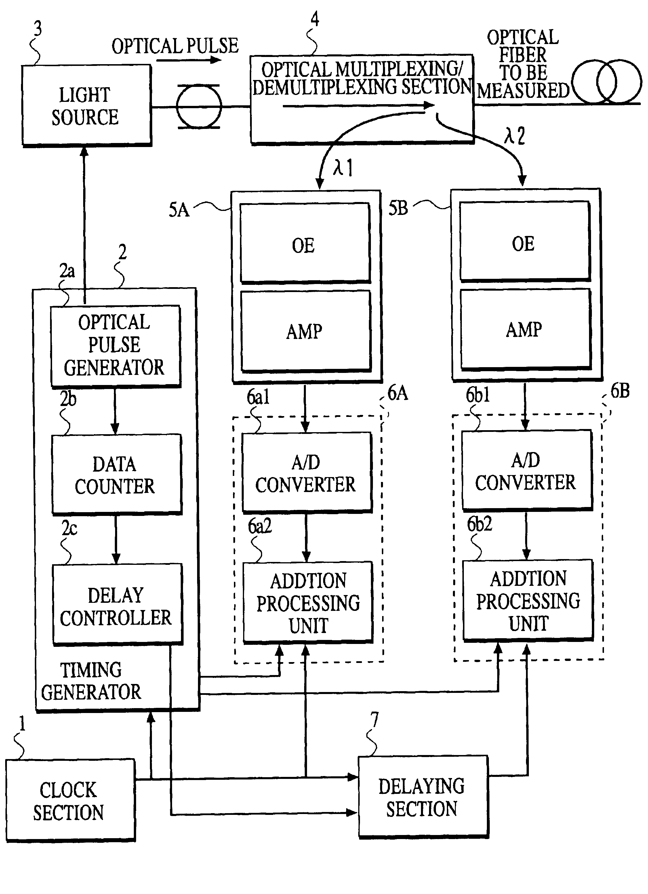
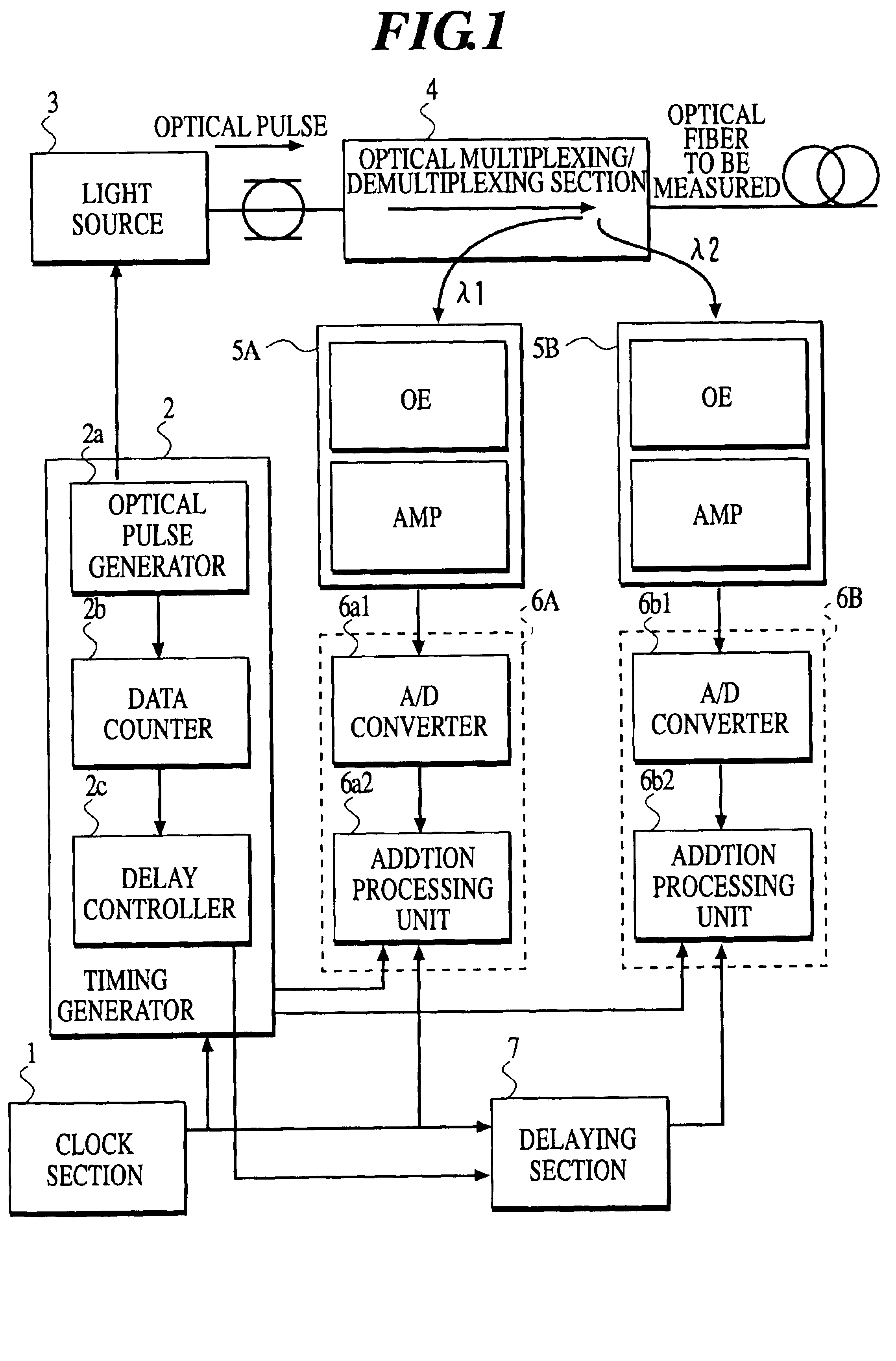
At first, description will be made about a first embodiment. FIG. 1 is a block diagram for illustrating a main configuration of an optical pulse testing device according to the first embodiment. In FIG. 1, a reference numeral 1 represents a clock section. A reference numeral 2 represents a timing generator. A reference numeral 3 represents a light source. A reference numeral 4 represents optical multiplexing / demultiplexing section. Each of reference numerals 5A and 5B represents a returned light receiving section. Each of reference numerals 6A and 6B represents a returned light detecting section. A reference numeral 7 represents a delaying section. Incidentally, the optical pulse testing device according to the first embodiment measures a particular property of an optical fiber to be measured, using returned lights having wavelengths .lambda.1 and .lambda.2, respectively, that are obtained from the optical fiber to be measured, when inputting an optical pulse into the optical fiber ...
second embodiment
Next, description will proceed to an optical pulse testing device according to a second embodiment of the present invention. Incidentally, the optical pulse testing device of the second embodiment emits a selected one of a plurality of optical pulses which have wavelengths different from one another. The optical pulse testing device of the second embodiment receives the returned light of single wavelength that is based on the selected optical pulse having a particular wavelength, to measure the property of the optical fiber to be measured. In following description, the parts similar to the first embodiment are designated by like reference numerals in the second embodiment and description will be omitted.
FIG. 3 is a block diagram for illustrating a main configuration of the optical pulse testing device according to the second embodiment of the present invention. A timing generator 2A comprises a delay controller 2d which is different in structure from the delay controller 2c of the t...
PUM
| Property | Measurement | Unit |
|---|---|---|
| wavelengths | aaaaa | aaaaa |
| phase-shift | aaaaa | aaaaa |
| phase shift | aaaaa | aaaaa |
Abstract
Description
Claims
Application Information