Push-pull output driver

a push-pull output and driver technology, applied in the direction of logic circuits, pulse techniques, reliability increasing modifications, etc., can solve the problems of increasing the unacceptable of push-pull shoot-through noise and the corresponding charge dump via by-pass capacitor, and the acceptance of brute force methods. , the effect of increasing the noise of push-pull shoot-through and the acceptance of by-pass capacitors

Inactive Publication Date: 2004-08-24
RAMBUS INC
View PDF5 Cites 28 Cited by
  • Summary
  • Abstract
  • Description
  • Claims
  • Application Information

AI Technical Summary

Problems solved by technology

In a digital system, this shoot-through phenomenon is well understood and results in considerable noise being transmitted onto the bus, absent some design remedy.
Unfortunately, as bus systems are required to run at ever increasing data rates this brute force method of dealing with shoot-through becomes less and less acceptable.
As DDR memory systems and similar data communication systems push the envelop for high-speed data transfer, push-pull shoot-through noise and the corresponding charge dump via by-pass capacitors becomes increasing unacceptable.
However, such pre-driver sensing techniques do not account for PVT

Method used


Image

  • Push-pull output driver
  • Push-pull output driver
  • Push-pull output driver

Examples


Embodiment Construction

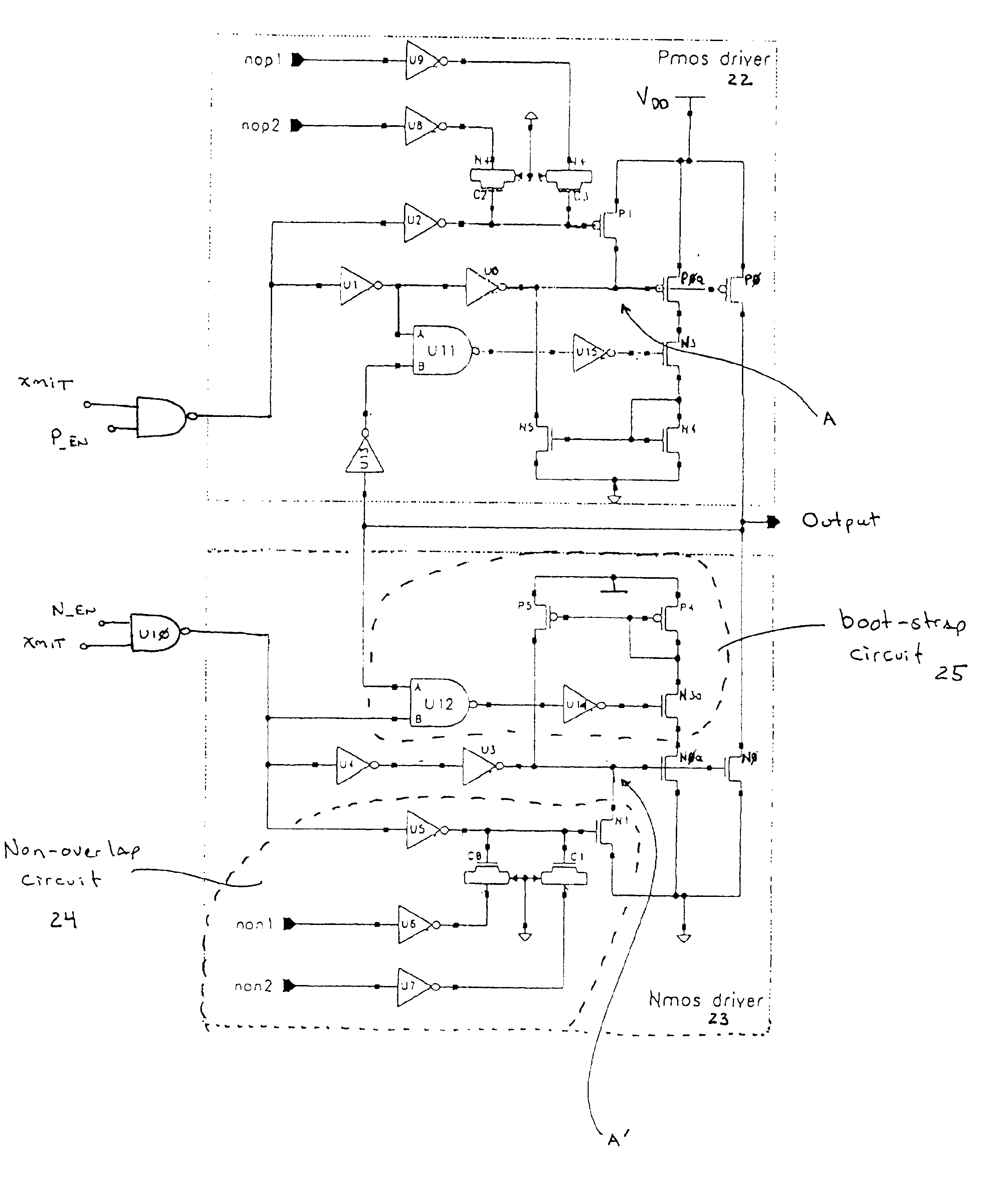
FIG. 4 illustrates one embodiment of the present invention and includes the combination of a pre-driver circuit and a push-pull driver. The push-pull driver portion of the circuit comprises the combination of PMOS transistor P0 and NMOS transistor N0 connected between voltage source V.sub.DD and ground. The remainder of the circuit shown in FIG. 4 is one example of an improved pre-driver circuit designed according to the dictates of the present invention. This particular embodiment follows the conventional approach of open loop control for the push-pull driver. No voltage waveform sensing is used, but timing relationships established by a process detector, such as a DLL, are used to provide improved non-overlap protection.

Of note, the PMOS driver 22 and NMOS driver 23 are open drain structures. When connected in series, (i.e., when connecting the drains of PMOS driver 22 and NMOS driver 23, and connecting PMOS driver 22 to V.sub.DD and NMOS driver 23 to ground), PMOS driver 22 and N...


PUM


Abstract

An improved, open-loop push-pull driver is described. Closed-loop feedback loop techniques for control of the push-pull driver are described. These techniques are particularly well adapted to control shoot-through current in a push-pull driver circuit.

Description

1. Field of the InventionThe present invention relates to drive circuits (or drivers). More particularly, the present invention defines an improved push-pull driver having edge conditioning and non-overlap control. The present invention further describes circuits and techniques for actively tuning the output of a push-pull driver.2. Description of the Related ArtPush-pull circuits are well known and have been adapted to digital and analog applications as varied as stepping motor control, audio loudspeakers, and memory systems. In the present context, push-pull circuits have been used in bus systems including one or more devices that output data onto a common bus. As used throughout, the term "bus" refers to one or more conductive paths communicating electrical signals between two points.Push-pull circuits have excellent drive characteristics. That is, push-pull circuits routinely provide clean rising and falling edges for high speed data signals being driven onto a bus. This capabil...

Claims


Application Information

Patent Timeline
IPC IPC(8): H03K19/00H03K17/16H03K19/017H03K19/01
CPCH03K17/166H03K19/0013H03K19/01735
Inventor NGUYEN, HUY M.LAU, BENEDICTVU, ROXANNE
Owner RAMBUS INC
Why Eureka
Try Eureka