Failsafe differential amplifier circuit

a technology of differential amplifier circuit and failure safety, which is applied in the direction of differential amplifier, amplifier with semiconductor devices/discharge tubes, logic circuits, etc., can solve problems such as unbalanced return current, inability to balance, and possible output distortion

Inactive Publication Date: 2004-08-24
SEMICON COMPONENTS IND LLC
View PDF3 Cites 73 Cited by
  • Summary
  • Abstract
  • Description
  • Claims
  • Application Information

AI Technical Summary

Problems solved by technology

But partial shorts or opens may lead to invalid input signals.
But, such an offset may unbalance return currents, distort the output and possibly load and reduce the input signal amplitude.
One limitation of this circuit is that the fail safe timer must swi...

Method used


Image

  • Failsafe differential amplifier circuit
  • Failsafe differential amplifier circuit
  • Failsafe differential amplifier circuit

Examples


Embodiment Construction

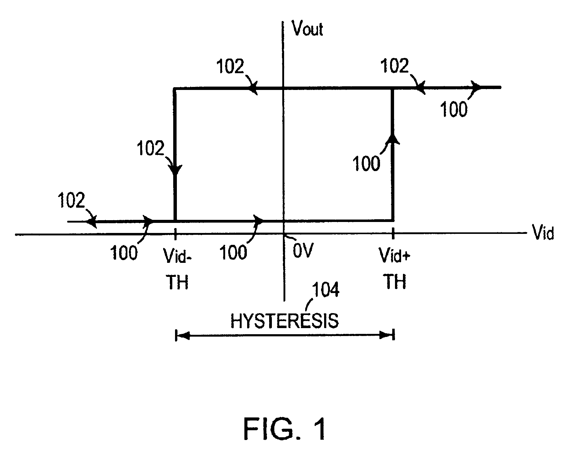
. 1 shows a basic hysteresis curve found in virtually all differential signal receivers. The horizontal axis represents a positive going differential signal, Vid, and the vertical axis represents the output signal going from 0 to +Vcc. A negative differential signal starting at 100 increases until Vid+ threshold is reached whereupon the output goes high. The Vid then might travel negative 102 with the output remaining high until the Vid- threshold is reached whereupon the output goers low. The difference between the Vid+ and the Vid- is the hysteresis 104 built into the circuit. The need for hysteresis is due to the differential input sensitivity of the amplifier. Without hysteresis an amplifier cannot accurately decide the state of a signal if it falls within the input sensitivity region. There is also a possibility of amplifier becoming unstable and oscillating if a signal remains in this undefined region. It is possible to add an additional hysteresis by design to further increas...


PUM


Abstract

Differential input fail safe circuitry is disclosed that detects missing or too low differential signals combined with a frequency lower than a frequency limit where a final safe condition is detected and signaled. The output signal form the fail safe circuitry is held in a given state that is an invalid representation of the differential input signal. A frequency detector, complementary offsetting auxiliary amplifiers with limit frequency roll offs are used to detect the fail safe condition. In addition a delay circuit is used that requires the fail safe condition to exist for some time before the fail safe circuit is active. Initialization circuitry ensures a proper power up conditions where the circuitry is enabled to detect the fail safe conditions and guarantees a reliable fail safe irrespective of the previous state of the signal.

Description

1. Field of the InventionThe present invention relates to logic differential amplifier circuits, and more particularly to such receivers incorporating fail-safe circuitry.2. Background InformationFail safe differential amplifiers or receivers provide a known output when an indeterminant or invalid input signal is present at the inputs. An invalid input signal generally occurs when the inputs are floating or three-stated, or shorted. But partial shorts or opens may lead to invalid input signals. In the face of such invalid input signals the receivers usually will oscillate, switch on noise or will be in an indeterminant state.Prior solutions have provided bias resistors at the inputs of the differential receiver to bias the inputs to a known condition by providing a de offset at the inputs. But, such an offset may unbalance return currents, distort the output and possibly load and reduce the input signal amplitude. Other solutions have biased the inputs of the receiver to Vcc with lo...

Claims


Application Information

Patent Timeline
IPC IPC(8): H03F3/68
CPCH03F3/68H03F3/45
Inventor PRADHAN, PRAVAS
Owner SEMICON COMPONENTS IND LLC
Why Eureka
Try Eureka