
High voltage generation circuit

a high-voltage generation and circuit technology, applied in the direction of power conversion systems, dc-dc conversion, instruments, etc., can solve the problems of back-bias voltage variance, increased voltage that exceeds the desired maximum high-voltage level, and reduced high-voltage levels

Inactive Publication Date: 2004-08-31
HYUNDAI ELECTRONICS IND CO LTD
View PDF6 Cites 16 Cited by
  • Summary
  • Abstract
  • Description
  • Claims
  • Application Information

AI Technical Summary

Benefits of technology

The solution effectively stabilizes high-voltage levels, reducing stress on memory cells and improving cell refresh properties by precisely controlling the activation of high-voltage pumps, thus maintaining a stable voltage range and minimizing voltage fluctuations.

Problems solved by technology

First, the level of high voltage is reduced, over time, to a non-conforming level.
During an actual pumping operation, after high-voltage level is detected, feedback to the high-voltage pump control signal VPPEN causes a delay, resulting in an increased voltage that exceeds a desired maximum high-voltage level.
Accordingly, the conventional high-voltage generation circuit suffers from the drawback that if the high-voltage level is greatly varied, an excessive level of stress may be applied to the memory cell causing a back-bias voltage variance.
Such a variance is due to the coupling of well capacitance and results in a degraded cell refresh property.

Method used


Image

  • High voltage generation circuit
  • High voltage generation circuit
  • High voltage generation circuit

Examples


Embodiment Construction

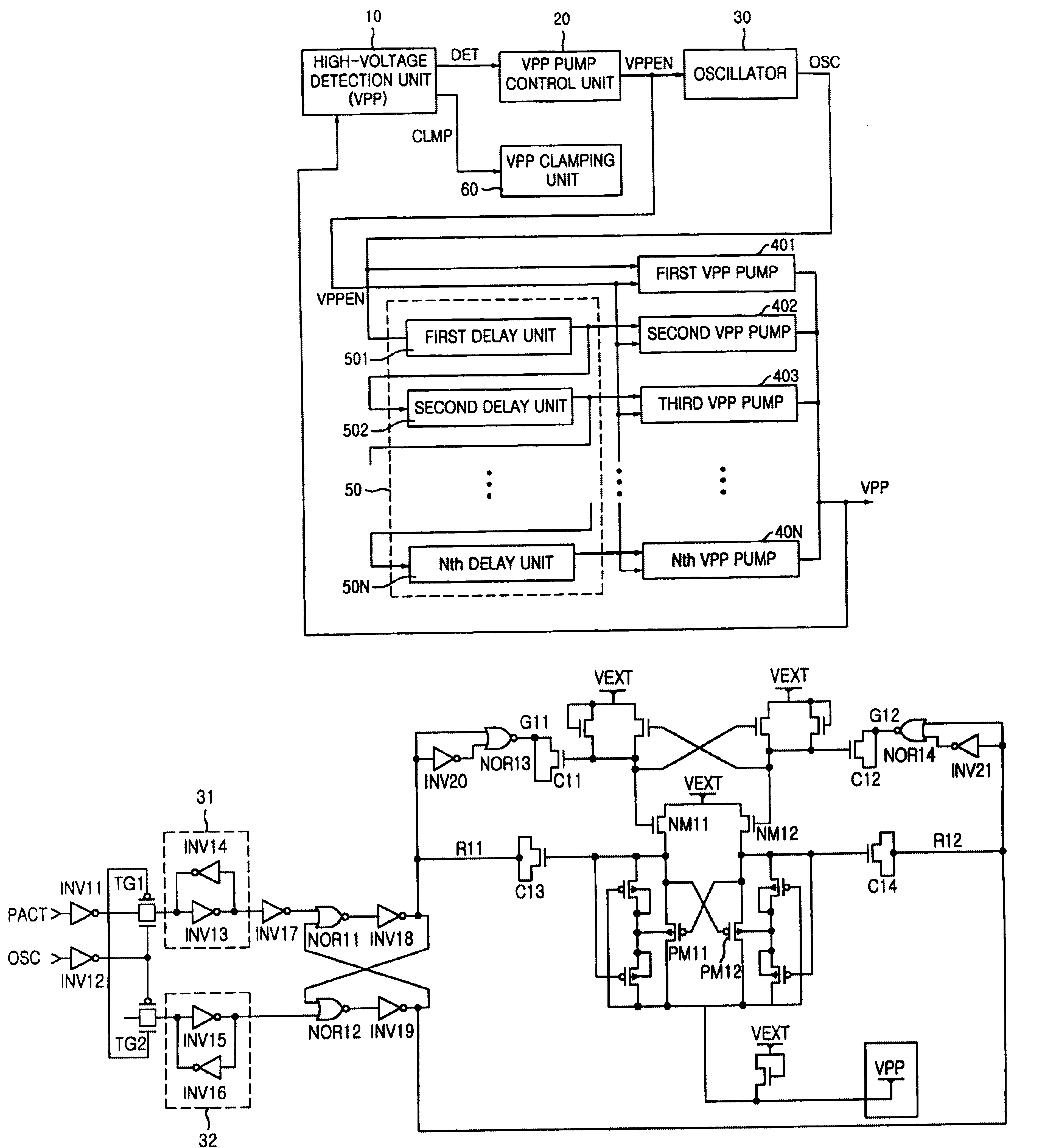
FIG. 4 is a schematic block diagram of a high-voltage generation circuit in accordance with a specific embodiment of the present invention. As shown in this FIG., the high-voltage generation circuit of the present invention comprises a high-voltage level detection unit 10, a high-voltage pump control unit 20, an oscillator 30, a plurality of high-voltage pumps 401-40N, a sequential delay unit 50 and a high-voltage high voltage clamping unit 60.

High voltage level detection unit 10 detects a level of high-voltage provided externally. Unit 10 outputs a detected signal DET when a minimum voltage level is obtained and a clamping active signal CLMP upon detecting level exceeding a maximum level. High-voltage pump control unit 20 generates a high-voltage pump control signal VPPEN in response to the detected signal DET from high-voltage level detection unit 10. Oscillator 30 generates a pulse signal OSC for driving the plurality of high-voltage pumps 401-40N in response to the high-voltage ...


PUM


Abstract

The present invention is a high-voltage generation circuit configured to sequentially activate a plurality of high-voltage pump circuits to precisely pump a level of high voltage. In one embodiment, the high-voltage generation circuit includes a high-voltage level detection unit for outputting a high-voltage detected signal, a high-voltage pump control unit for generating a control signal responsive to a detected signal, an oscillator for generating a pulse signal for driving a plurality of high-voltage pumps, a sequential delay unit for sequentially delaying the pulse signal from the oscillator, and a plurality of high-voltage pumps for pumping the high voltage based on a delayed pulse signal and the control signal.

Description

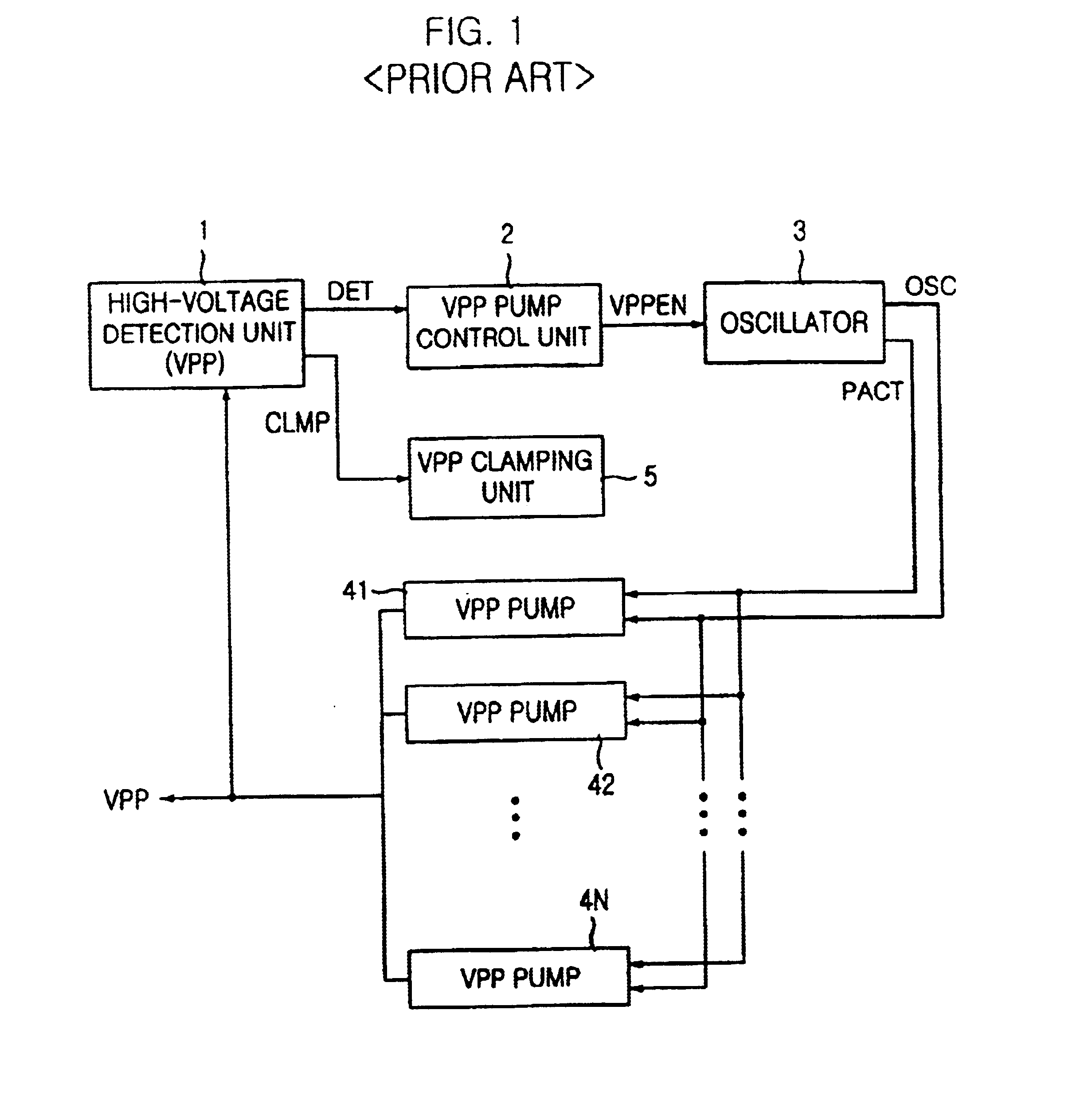
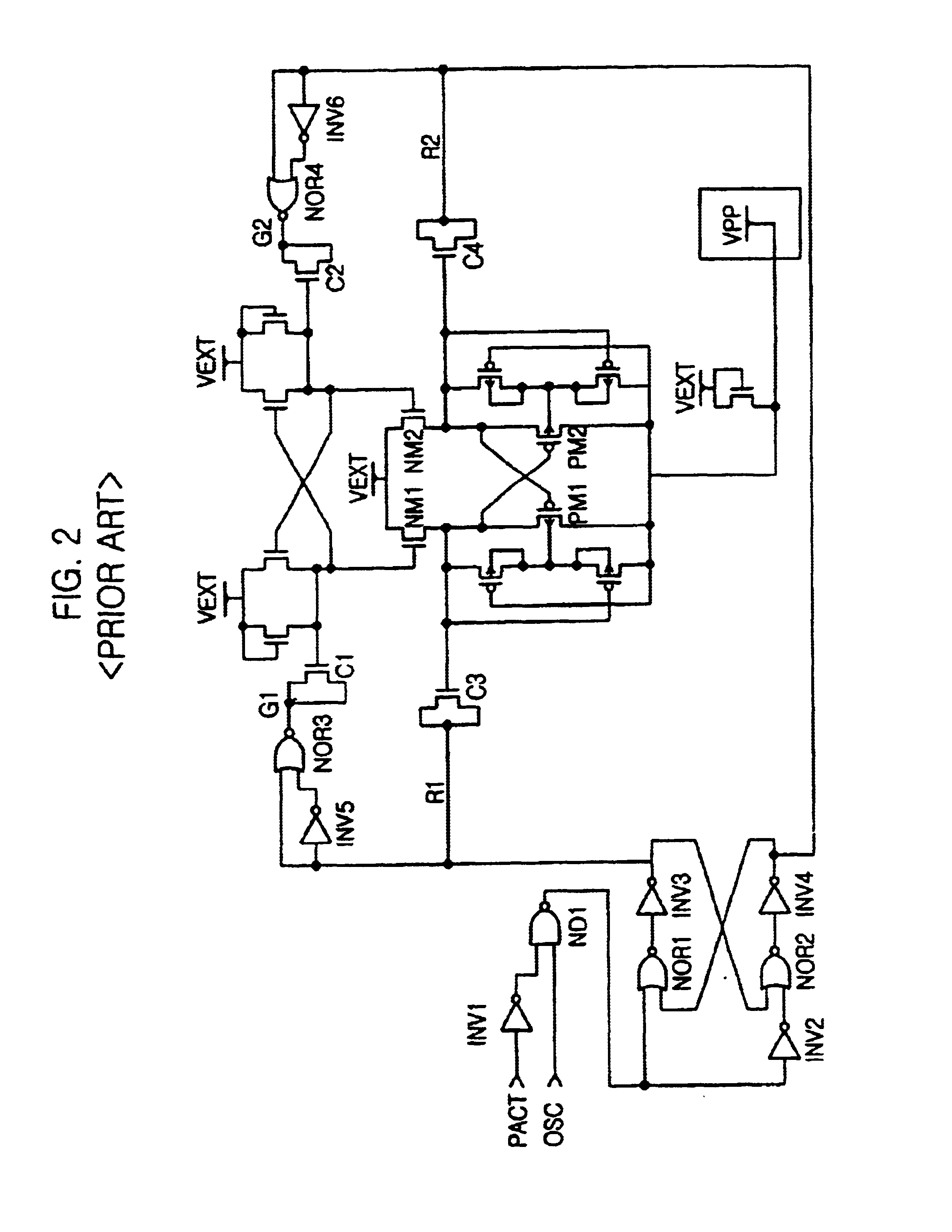
CROSS-REFERENCES TO RELATED APPLICATIONSThis application claims priority from Korean Application, entitled "High Voltage Generation Circuit" Application No. 2000-36944 and filed on Jun. 30, 2000 and incorporates by reference its disclosure for all purposes.1. Field of the InventionThe present invention relates to a high-voltage generation circuit and in particular, to a high-voltage generation circuit which is capable of sequentially enabling a high-voltage pump to obtain high-precision pumping, to thereby generate a stabilized high voltage.2. Description of the Prior ArtIn a semiconductor device using an external power supply, a high-voltage generation circuit is widely used. Because the high-voltage generation circuit generates a voltage higher than the external power supply of the threshold voltage of a transistor, the circuit can compensate for a loss of threshold voltage.FIG. 1 is a schematic block diagram of a conventional high-voltage generation circuit. As shown in this FIG....

Claims


Application Information

Patent Timeline
Patent Type & Authority Patents(United States)
IPC IPC(8): H02M3/07H02M3/04G11C5/14
CPCH02M3/073H02M2003/077H02M3/077G11C5/14
Inventor LEE, SANG-KWONKIM, JOON-HONAM, YOUNG-JUNCHO, KWANG-RAELEE, BYUNG-JAE
Owner HYUNDAI ELECTRONICS IND CO LTD
Learn More