Electrophoretic device, driving method of electrophoretic device, and electronic apparatus

a technology of electrophoretic device and electrophoretic display device, which is applied in the direction of static indicating device, instruments, optical elements, etc., can solve the problems of insufficient visibility and contrast characteristics of electrophoretic display device, and achieve the effect of improving visibility and contrast characteristics

Inactive Publication Date: 2004-09-07
E INK CORPORATION
View PDF5 Cites 59 Cited by
  • Summary
  • Abstract
  • Description
  • Claims
  • Application Information

AI Technical Summary

Benefits of technology

is to provide an electrophoretic device which is capable of improving the visibility and the contrast characteristic and maintaining the distribution condition of electrophoretic particles for a long time, and suitable for a display device, and a method for driving the electrophoretic device, and an electronic apparatus having the electrophoretic device.
In the driving method of the above electrophoretic device and the above electrophoretic device, the mixture of a plurality of substances is used as the dispersion medium, and the mixture of low mutual solubility of the plurality of substances is used. The mutual solubility of the plurality of substances forming the dispersion medium is small, and the liquid does not become homogeneous, and thus, the transmissivity is degraded. For example, if the electrophoretic particles are located on the distal side from, for example, the observation side, the electrophoretic particles cannot be visually recognized from the observation side. Thus, the contrast of the electrophoretic particles with the dispersion medium can be ensured, and the visibility can be improved.
At least one of the plurality of substances constituting the dispersion medium is non-fluid at the normal temperature and is fluid at the non-normal temperature, and as a result, the dispersion medium is non-fluid at the normal temperature. Thus, the position of the electrophoretic particles at this time can be maintained. Therefore, if used as the electrophoretic display device, the dispersion medium is heated by, for example, the heating means, and the electrophoretic particles are electrophoretically operated in a non-normal temperature to perform a desired display. After that, the dispersion medium is cooled by a cooling means not shown in the figure to be maintained at the normal temperature, and the display content can be maintained thereby.
The light scattering intensity is increased by consisting the dispersion medium of a plurality of substances much different in the refractive index, and the visibility and the contrast characteristic can be improved more as the difference in the refractive index is larger.
Dispersibility of the electrophoretic particles in the dispersion medium can be improved by mixing the dispersing agent in the dispersion medium, the zeta potential self-excited by the electrophoretic particles can be increased, the electrophoretic speed of the electrophoretic particles in applying the voltage can be increased, and as a result, the response speed can be increased.
This electronic apparatus can ensure the contrast of electrophoretic particles with the dispersion medium by providing the electrophoretic device as a display body, and can improve the visibility.

Problems solved by technology

However, in some combinations of the display color of the dispersion medium with the display color of the electrophoretic particles, the display color of the electrophoretic particles can be observed by transmitting the colored dispersion medium if electrophoretic particles are located opposite to observation side when viewed from the observation side of the display device, and in particular, the display color of the electrophoretic particles is dark, for example, blackish, its trend becomes conspicuous, and the electrophoretic display device has not been sufficient in visibility, contrast characteristic, etc.

Method used


Image

  • Electrophoretic device, driving method of electrophoretic device, and electronic apparatus
  • Electrophoretic device, driving method of electrophoretic device, and electronic apparatus
  • Electrophoretic device, driving method of electrophoretic device, and electronic apparatus

Examples


examples

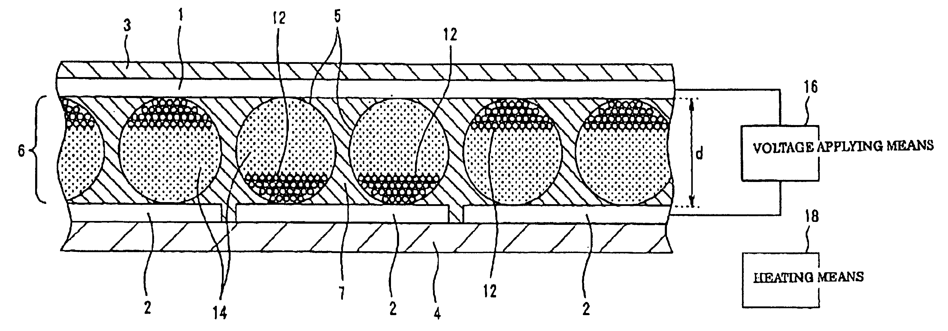
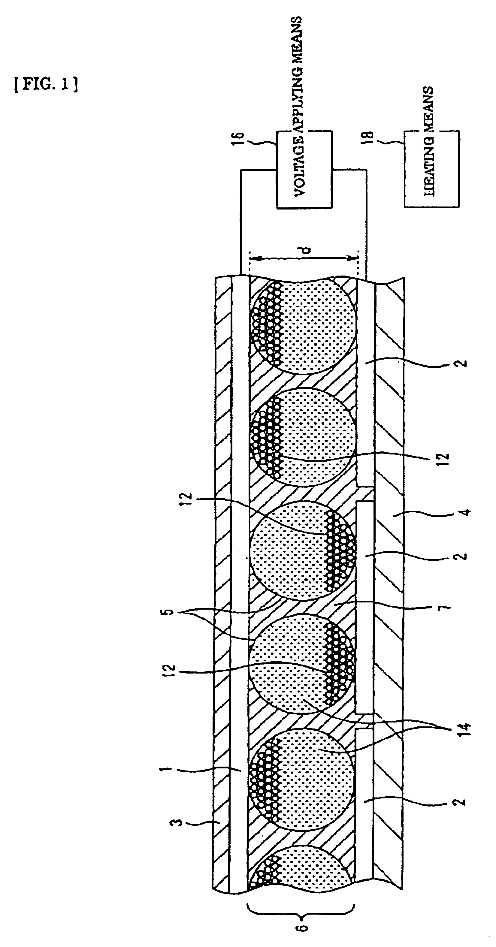
Carbon black particles of 5 g having the grain size of 0.5 .mu.m for the electrophoretic particles 12, oleic acid of 0.5 g for the dispersing agent, hexadecyl alcohol of 10 g having the melting point of 48.degree. C. for the dispersion medium 14 and paraffin wax of 90 g having the melting point of 50.degree. C. for the mixture solvent are heated and mixed for one hour under the condition of 200.degree. C. by a homogenizer, and the dispersive solution was obtained.

The micro capsule 5 containing the dispersive solution having the grain size of 50 .mu.m and formed of gum arabic was prepared by using an interfacial deposit method.

Next, two transparent sheets having conductive transparent electrodes (ITO film) thereon constituting the transparent electrodes 1 and 2 were prepared with the transparent electrode surfaces facing each other, and the micro capsule 5 prepared between these transparent electrode films was rolled by a roller so as not to damage micro capsule 5 and arrayed on a pl...


PUM

PropertyMeasurementUnit
melting pointsaaaaaaaaaa
grain sizeaaaaaaaaaa

Abstract

There is provided an electrophoretic device which comprises an electrophoretic layer containing dispersion medium and electrophoretic particles dispersed in the dispersion medium, controls the position of the electrophoretic particles according to the electric potential applied to electrodes, and can maintain the electrophoretic particles at a desired position for a long time by using the dispersion medium formed of mixture consisting of a plurality of substances having small mutual solubility.

Description

The present invention relates to an electrophoretic device, a driving method thereof, and an electronic apparatus provided therewith, and more in particular, it relates to an electrophoretic device excellent in visibility and contrast characteristic and having consistent display maintaining characteristic for a long time, a driving method thereof, and an electronic apparatus provided therewith.DESCRIPTION OF THE RELATED ARTConventional electrophoretic display devices utilizing changes in a distribution condition of electrophoretic particles dispersed in dispersion medium by applying the voltage between a pair of electrodes facing each other including one in which electrophoretic dispersive solution containing dispersion medium and electrophoretic particles is placed in an area which is provided, for example, on a base body and demarcated by bulkheads, and is used as an electrophoretic layer, and one in which a micro capsule accommodating electrophoretic dispersive solution therein i...

Claims


Application Information

Patent Timeline
Patent Type & Authority Patents(United States)
IPC IPC(8): G02F1/01G02F1/167G01N27/447G02F1/16757
CPCG02F1/167G02F1/16757
Inventor KAWAI, HIDEYUKIYAMAMOTO, HIROKAZU
Owner E INK CORPORATION
Why Eureka
Try Eureka