

Friction reducing ship and method for reducing frictional resistance
a friction reduction and friction technology, applied in vessel construction, special-purpose vessels, machines/engines, etc., can solve the problems of loss of a part of the energy saving achieved, ineffective covering, and ineffective extension of the flow of micro-bubbles to the center section of the bottom surfa
- Summary
- Abstract
- Description
- Claims
- Application Information
AI Technical Summary
Benefits of technology
Problems solved by technology
Method used
Image

Examples
embodiment 1
A: Embodiment 1
In the following, Embodiment 1 of this invention for a friction reducing ship and a method of reducing the frictional forces will be explained with reference to the drawings.
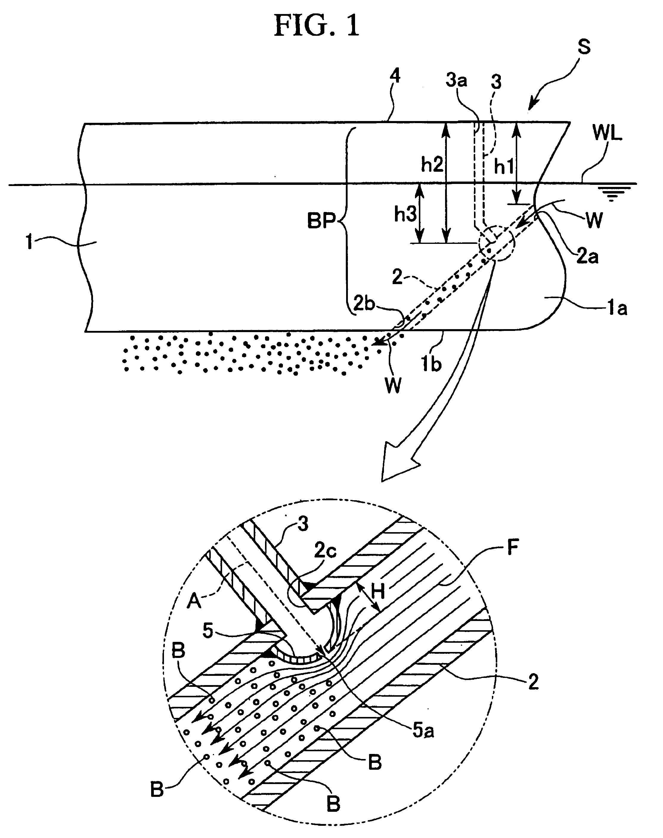
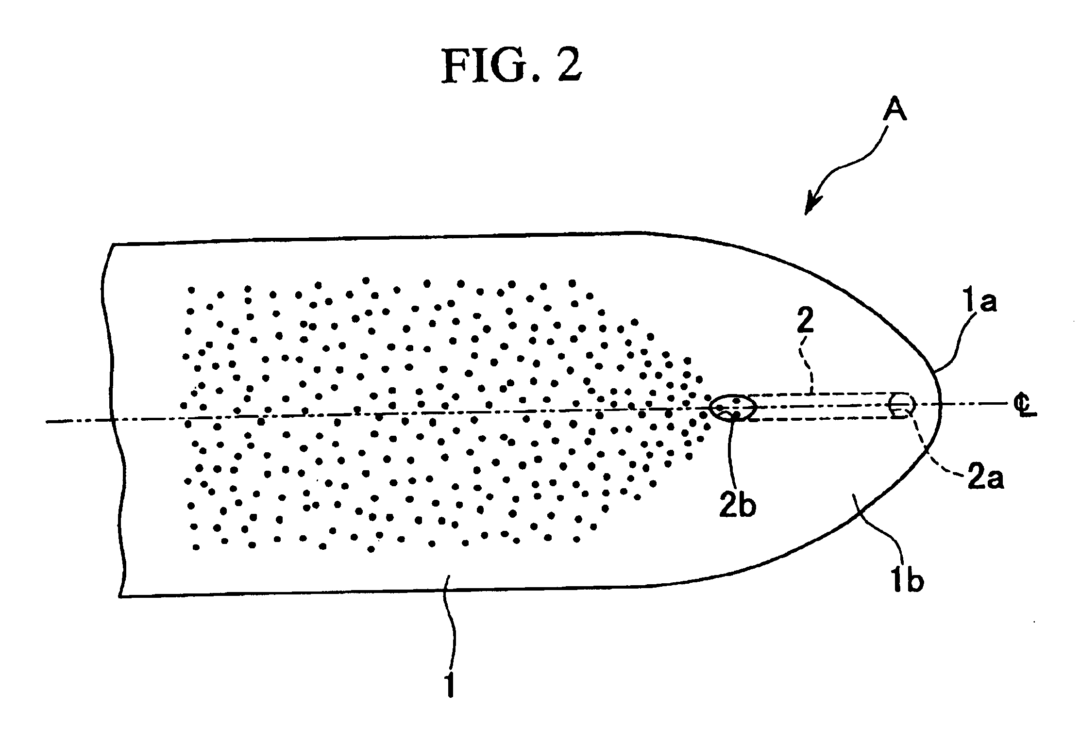
FIG. 1 is a side view (starboard side) of key sections of a friction reducing ship S in this embodiment and an enlarged view of a section, and FIG. 2 is a bottom view. In these diagrams, a reference numeral 1 relates to the external hull plate of the ship; 2 to a water inlet pipe (water passage); 3 to an air intake pipe (air passage); 4 to the deck; 5 to an ejection part; A to air; B to a micro-bubble; F to a flowline; W to seawater (water); WL to a waterline. Here, of these structural elements, the water inlet pipe 2, air intake pipe 3 and the ejection part 5 comprise the bubble generation means BP.
In this friction reducing ship S, as shown in FIG. 1, the water inlet pipe 2 is provided at an angle to extend from the bow 1a at the water line WL on the external hull 1 to the bottom surface 1b, and ...
embodiment 2
B: Embodiment 2
In the following, an example of applying the method of reducing frictional resistance and friction reducing ship to a bulk ship such as a tanker or container ship will be explained with reference to the drawings. In FIG. 8A, M refers to a friction reducing ship, 10 to a ship body, 11 to a bubble generation apparatus, 12 to outer hull plate (submerged surface), 13 to a screw, 14 to a rudder, and 15 to the water surface (waterline).
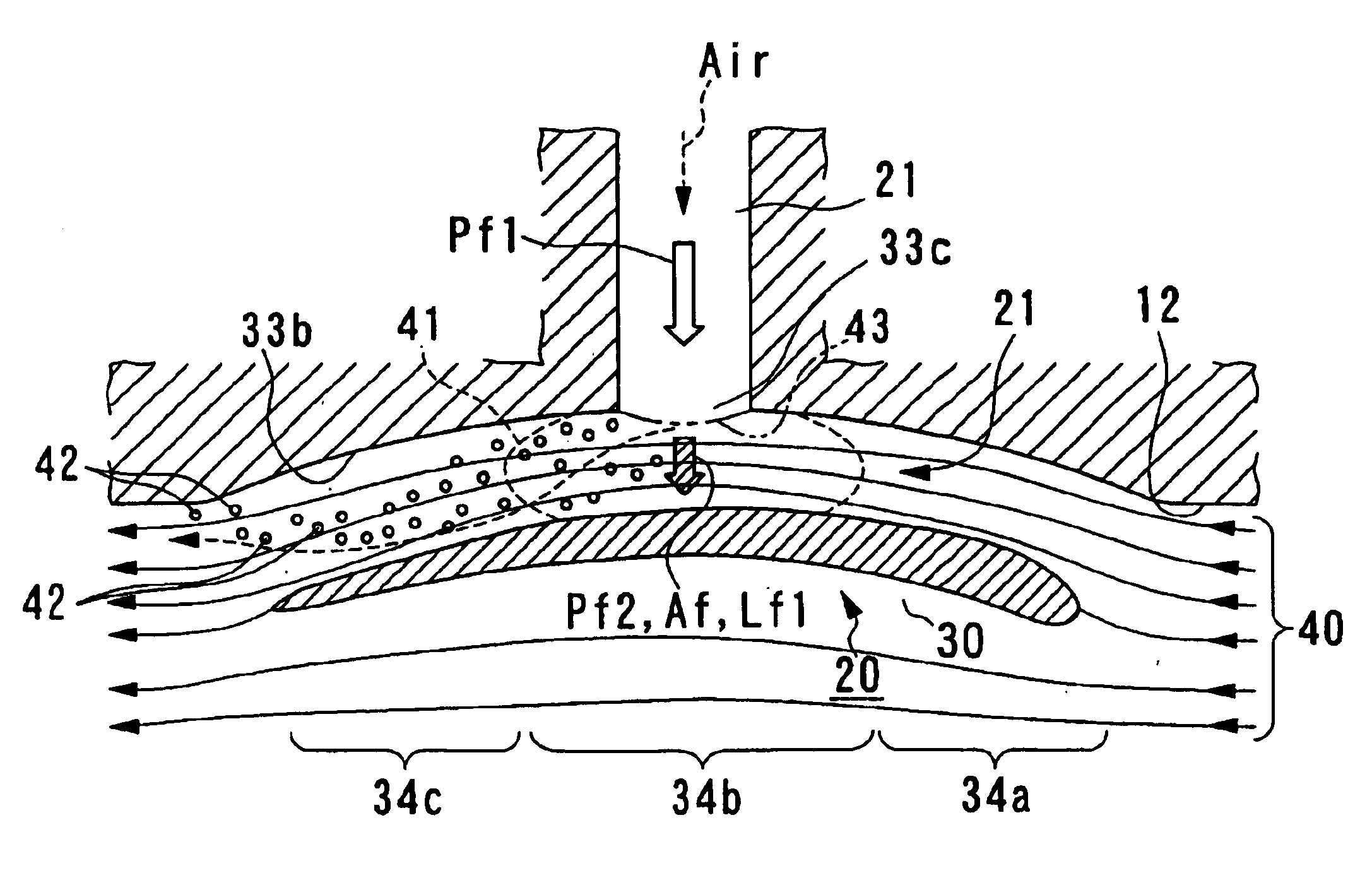
A bulk ship suitable for adopting as a friction reducing ship M is a VLCC (very large crude oil carrier) and the like, because, the outer hull plate 12 (submerged surface) of the ship below the waterline 15 is made relatively large compared with other types of ship. Further, the bubble generation apparatus 11 is disposed in the fore-section of the ship body 10. As shown in FIG. 8B, the bubble generation apparatus 11 is provided with a negative pressure forming section 20 disposed in the submerged surface 12, and a fluid passage 21 passing thr...
embodiment 3
C: Embodiment 3
In the following, an application of a friction reducing ship in Embodiment 3 to a bulk ships such as a tanker or container ship will be explained.
In FIG. 14A, M refers to a friction reducing ship, 10 to a ship body, 11 to a bubble generation apparatus, 12 to an external hull plate (submerged surface), 13 to a screw, 14 to a rudder, and 15 to a water surface (waterline). A bulk ship suitable for adopting as a friction reducing ship M is a VLCC (very large crude oil carrier) and the like, because the area of the bottom section in the external hull plate (submerged surface) 12 of the ship body below the waterline 15 is made larger relative to the lateral hull of the ship body. Further, the bubble generation apparatus 11 is disposed in the fore-section (bow section) of the ship body 10.
As shown in FIG. 14B, the bubble generation apparatus 11 is provided with a flow guiding body 20 disposed in the opening 12a provided in the bottom section, and an air induction pipe (AIP) ...
PUM
 Abstract
Description
Claims
Application Information