Electrophoretic display with sub relief structure for high contrast ratio and improved shear and/or compression resistance

a technology of sub relief structure and high contrast ratio, applied in the direction of electrographic process, static indicating device, instruments, etc., can solve the problems of poor scratch resistance, difficulties encountered, and own problems

Inactive Publication Date: 2004-09-21
E INK CALIFORNIA
View PDF119 Cites 93 Cited by
  • Summary
  • Abstract
  • Description
  • Claims
  • Application Information

AI Technical Summary

Benefits of technology

While the present invention has been described with reference to the specific embodiments thereof, it should be understood by those skilled in the art that various changes may be made and equivalents may be substituted without departing from the true spirit and scope of the invention. In addition, many modifications may be made to adapt a particular situation, materials, compositions, processes, process step or steps, to the objective, spirit and scope of the present invention. All such modifications are intended to be within the scope of the claims appended hereto.

Problems solved by technology

However, each of these has its own problems as noted below.
However, difficulties are encountered in many aspects including the formation of the partitions, the process of filling the display with the fluid, enclosing the fluid in the display and keeping the suspensions of different colors separated from each other.
The large microcapsule size results in a poor scratch resistance and a slow response time for a given voltage because a large gap between the two opposite electrodes is required for large capsules.
Also, the hydrophilic shell of microcapsules prepared in an aqueous solution typically results in sensitivity to high moisture and temperature conditions.
If the microcapsules are embedded in a large quantity of a polymer matrix to obviate these shortcomings, the use of the matrix results in an even slower response time and / or a lower contrast ratio.
However, the microencapsulation process in an aqueous solution imposes a limitation on the type of charge controlling agents that can be used.
Other drawbacks associated with the microcapsule system include poor resolution and poor addressability for color applications.
The display fluid within a conventional display prepared by the edge sealing adhesive method will leak out completely if the display is cut in any way, or if a hole is drilled through the display.
The damaged display will be no longer functional.
Without the microcup structure, it will be very difficult to prevent the fluids in adjacent areas from intermixing or being subject to cross-talk during operation.
Also, as the opening ratio increases, undesirable particle movement such as convection flow inside the cells becomes more significant and the display contrast ratio in fact decreases.
The image uniformity of the display also deteriorates if excessive undesirable movement is present.

Method used


Image

  • Electrophoretic display with sub relief structure for high contrast ratio and improved shear and/or compression resistance
  • Electrophoretic display with sub relief structure for high contrast ratio and improved shear and/or compression resistance
  • Electrophoretic display with sub relief structure for high contrast ratio and improved shear and/or compression resistance

Examples


Embodiment Construction

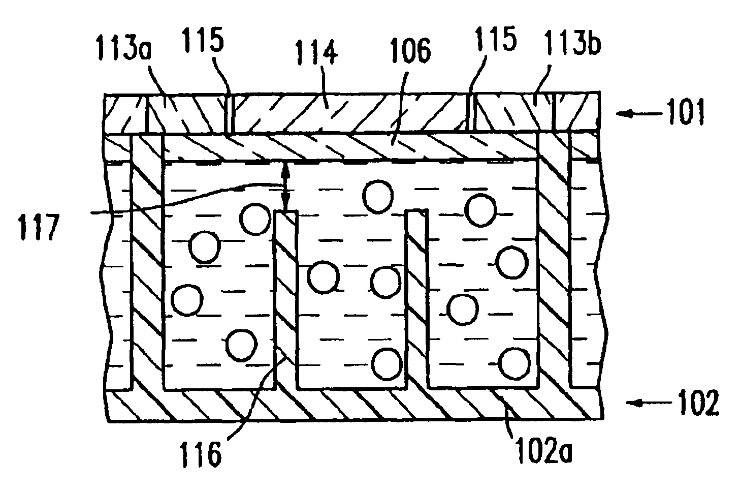
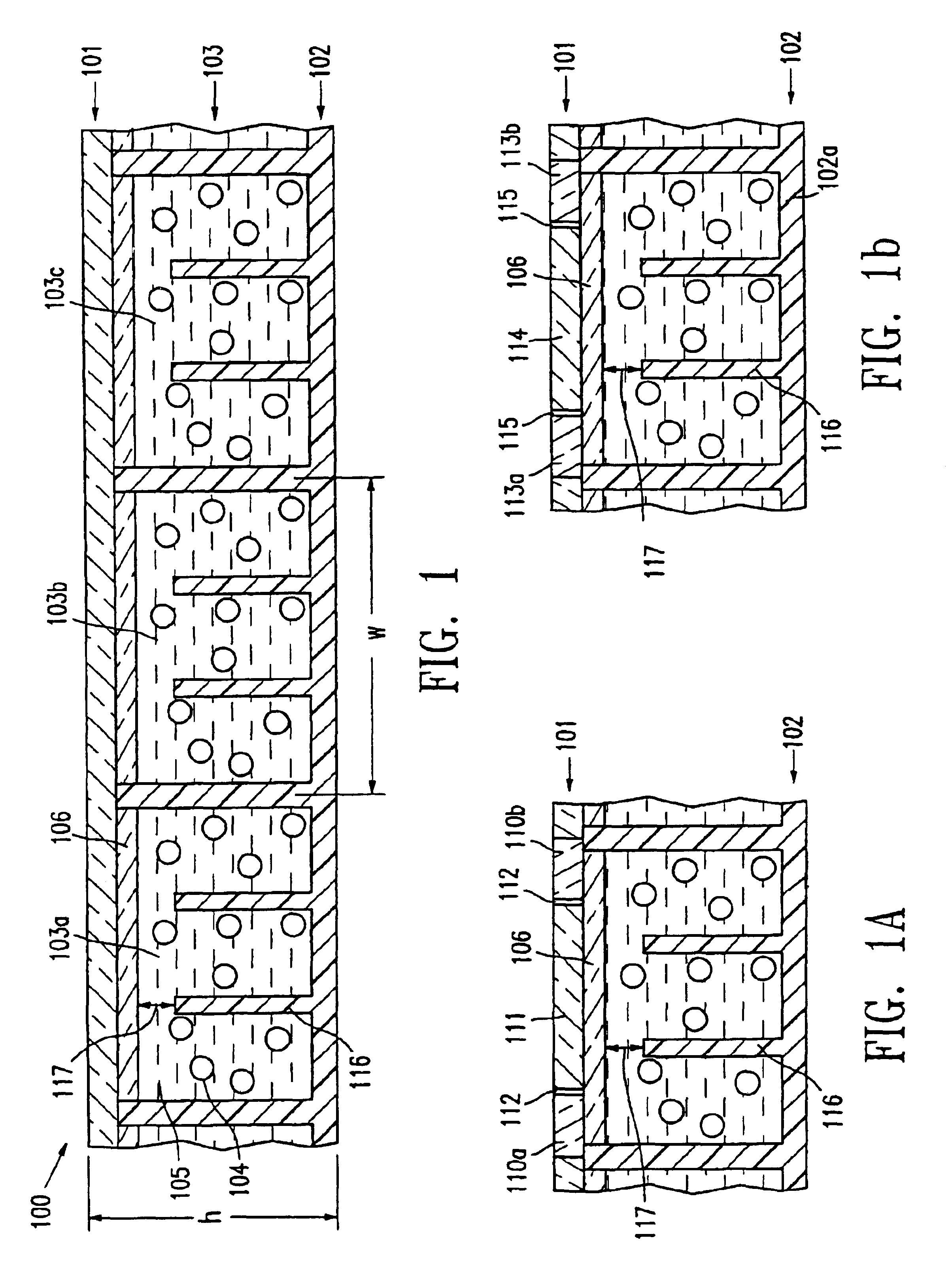
An electrophoretic display (100) of the present invention, as shown in FIG. 1, comprises a top transparent layer (101), one bottom layer (102) and a layer of isolated cells (103) enclosed between the two layers. The top transparent layer (101) is a transparent conductor film such as ITO on PET. The cells (103a, 103b and 103c) are filled with charged particles (104) dispersed in a dielectric solvent (105) and sealed with a sealing layer (106). The top transparent layer is usually laminated over the sealed cells with an adhesive layer.

In the display having an in-plane switching mode (FIG. 1a), the bottom layer (102) is an insulator substrate and the top electrode plate (101) comprises in-plane electrodes (110a and 110b) and a top electrode (111) between the two in-plane electrodes separated by gaps (112). Alternatively, the top layer may have only one in-plane switching electrode and one top electrode with a gap in between. In the display having a dual switching mode (FIG. 1b), the bo...


PUM

PropertyMeasurementUnit
widthaaaaaaaaaa
widthaaaaaaaaaa
widthaaaaaaaaaa

Abstract

This invention relates to an electrophoretic display comprising isolated cells of well-defined shape, size and aspect ratio which cells have internal sub relief structures and are filled with charged pigment particles dispersed in a dielectric solvent. The display shows an improved contrast ratio and resistance against shear and compression pressures. The display may have the traditional up / down switching mode, an in-plane switching mode or a dual switching mode.

Description

a) Field of the InventionThis invention relates to an improved electrophoretic display comprising isolated cells of well-defined shape, size and aspect ratio, and the cells have internal sub relief structures and are filled with charged particles dispersed in a dielectric solvent.The display may have the traditional up / down switching mode, the in-plane switching mode or the dual switching mode.b) Description of Related ArtThe electrophoretic display (EPD) is a non-emissive device based on the electrophoresis phenomenon influencing charged pigment particles suspended in a colored dielectric solvent. This general type of display was first proposed in 1969. An EPD typically comprises a pair of opposed, spaced-apart plate-like electrodes, with spacers predetermining a certain distance between the electrodes. At least one of the electrodes, typically on the viewing side, is transparent. For the passive type of EPDs, row and column electrodes on the top (the viewing side) and bottom plate...

Claims


Application Information

Patent Timeline
Patent Type & Authority Patents(United States)
IPC IPC(8): G02F1/01G02F1/167G02F1/13G02F1/1343
CPCG02F1/167G02F1/134363
Inventor LIANG, RONG-CHANGHOSSEINI, ABBASCHUANG, HSIAO-KEN
Owner E INK CALIFORNIA
Why Eureka
Try Eureka