Method for drilling bone, in particular for setting a pedicle screw, equipment, instrument and control device for implementing said method

a pedicle screw and bone technology, applied in bone drill guides, medical science, surgery, etc., can solve the problems of 25% of pedicle screws being ill-positioned, difficulty is further increased, and no satisfactory solution has been found

Inactive Publication Date: 2004-09-28
SPINEGUARD
View PDF4 Cites 222 Cited by
  • Summary
  • Abstract
  • Description
  • Claims
  • Application Information

AI Technical Summary

Problems solved by technology

The problem which arises with the instruments of the state of the art relates to the guiding of the drilling instrument, and more precisely to the choice of entry point and orientation of the drilling tool in order to avoid any risk of going beyond the pedicle.
The difficulty derives from the need to cross through cancellous bone while remaining in contact with cortical bone, it being essential to avoid a pathway that is too lateral which could injure the spinal cord or the spinal nerves.
The difficulty is further increased if the pedicle is deformed requiring the drilling instrument to emerge at one point of the pedicle and to return inside the pedicle beyond the deformation without harming innervated parts.
Clinical trials show that that no satisfactory solution has been found to this problem at the present time, and it would appear that 25% of pedicle screws are ill-positioned.
Detection of patient reaction is made by visual observation, which cannot guarantee a sufficiently fast reaction on the part of the surgeon.
In addition, the trigger threshold of the reaction is dependent upon the patient, upon patient condition, and cannot guarantee satisfactory reliability and sensitivity in detection.

Method used


Image

  • Method for drilling bone, in particular for setting a pedicle screw, equipment, instrument and control device for implementing said method
  • Method for drilling bone, in particular for setting a pedicle screw, equipment, instrument and control device for implementing said method
  • Method for drilling bone, in particular for setting a pedicle screw, equipment, instrument and control device for implementing said method

Examples


Embodiment Construction

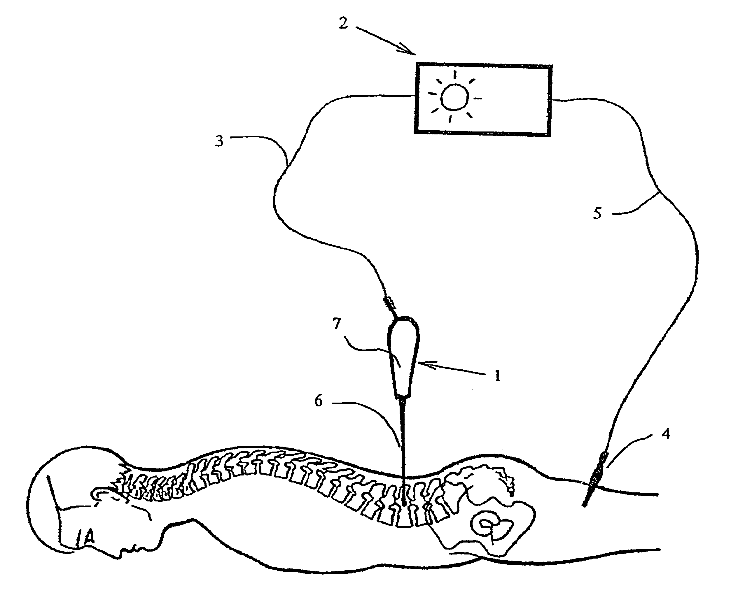
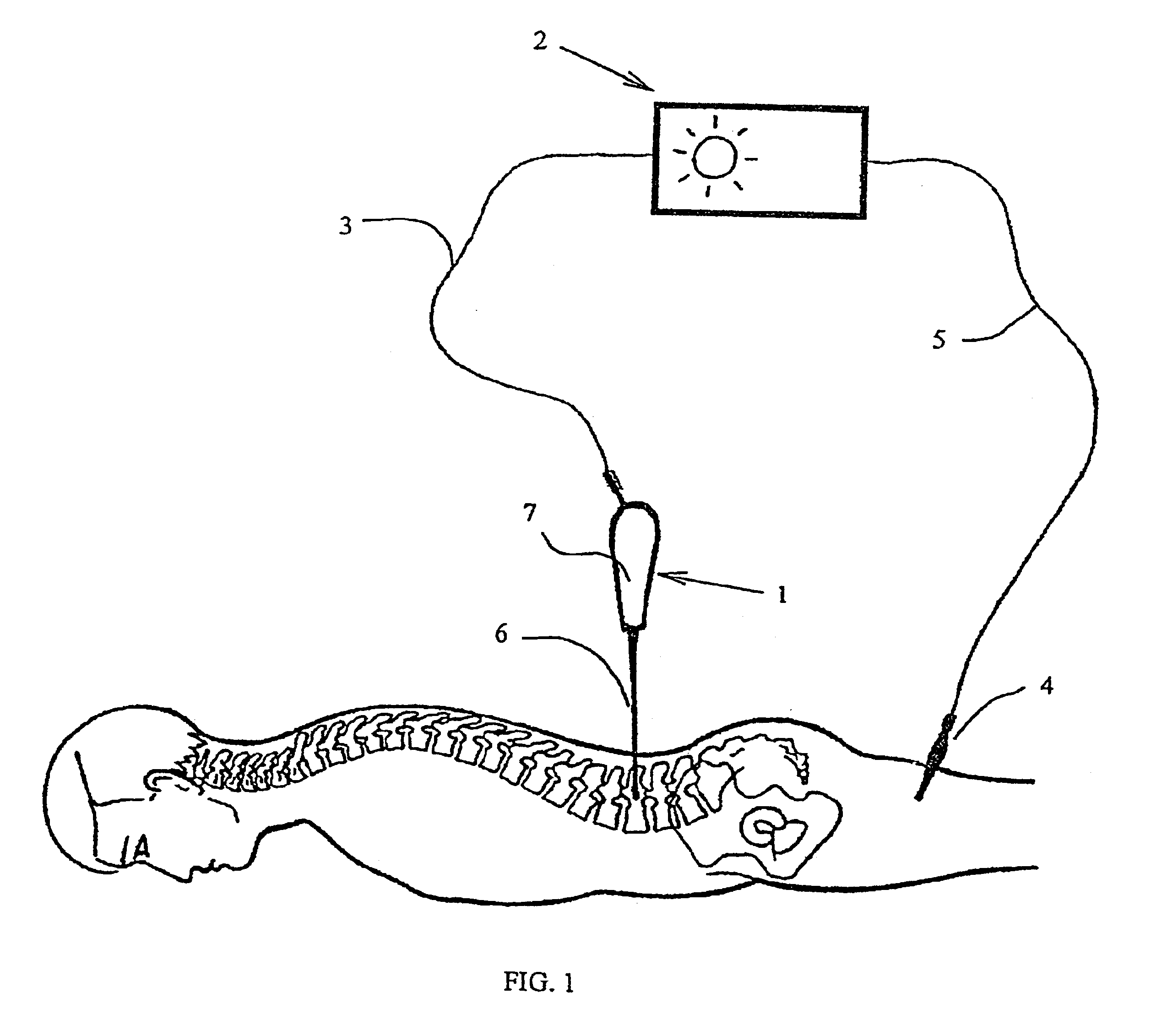
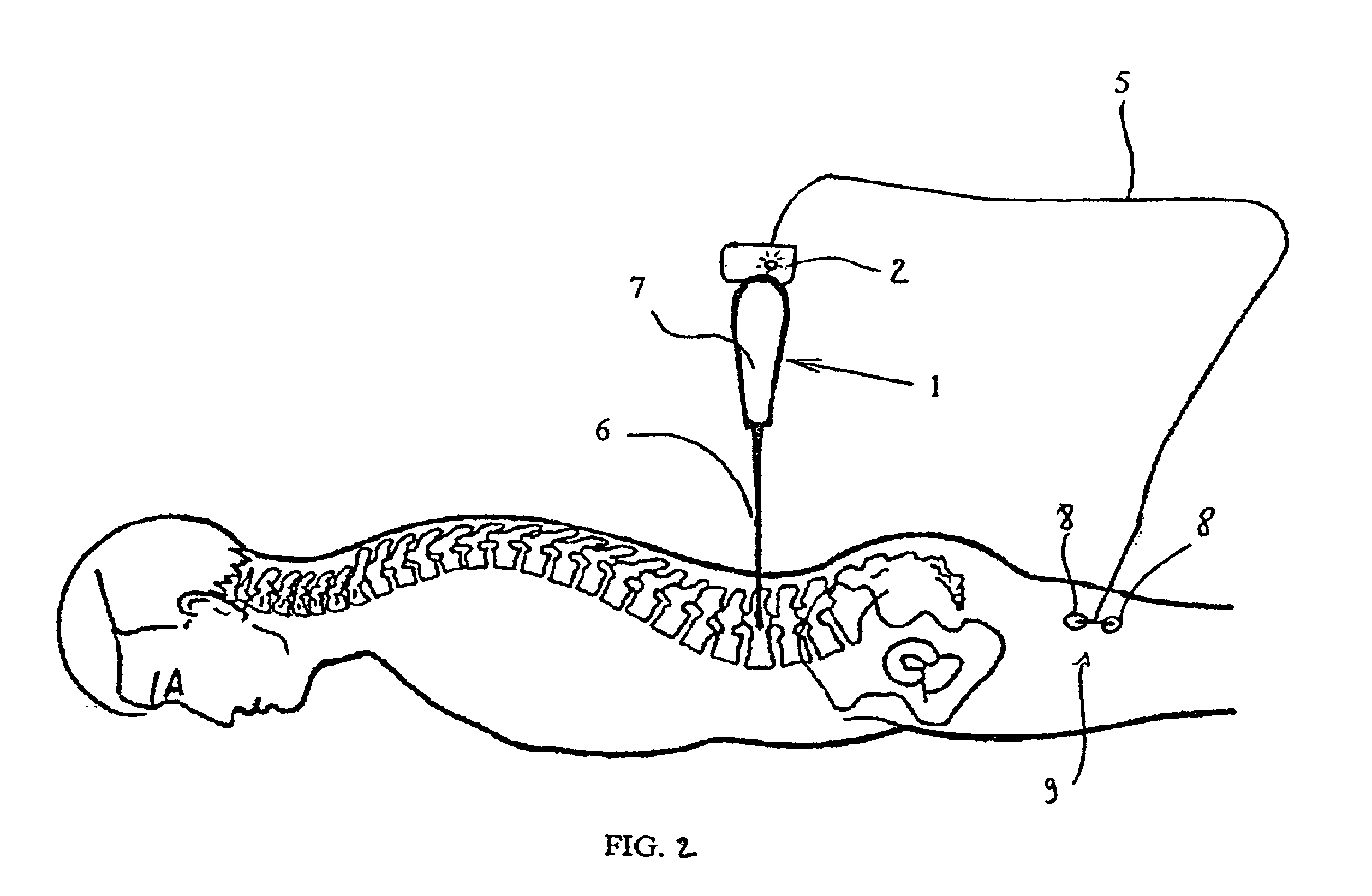
The equipment according to the first variant of embodiment of the invention, illustrated in FIG. 1, comprises a drilling instrument 1 connected to a control box 2 via a sterile electric cord 3. The control box 2 is also connected to a sensor, forming an electrode, formed of a fine needle 4, via another sterile electric cord 5.

The drilling instrument 1 comprises a drill-bit or metal drill forming a drilling tool 6 integral with a handle 7 that is fixed or comprises a motor. The connection between the electric cord 3 and the drilling tool 6 is made by means of a rotating electric connector or chuck in conductor material and a connecting terminal provided on the handle or on the motor unit of the drilling tool.

Control box 2 delivers an electric signal of low current and low voltage. This signal is constant with a frequency of 5 hertz or less, in order to allow the signal detected by the needle 4 to be correlated with the signal applied to the drilling tool 6 and to eliminate interferen...


PUM


Abstract

The present invention concerns a method and equipment for drilling bone, in particular for setting a pedicle screw using a manual or motorized drilling tool. The equipment includes a drilling instrument, a source of electric impulses and a connector for connecting the electric impulse source to the drilling instrument. The equipment includes at least one sensor for detecting a muscle signal either implanted in a muscle or placed on the skin in the vicinity of a muscle before and during drilling. An alert is produced in the event of detection by at least one sensor of a muscle signal correlated with the source of electric impulses connected to the drilling instrument.

Description

BACKGROUND OF THE INVENTIONThe present invention concerns the area of spinal surgery, more precisely the drilling of vertebral pedicles, in particular for setting pedicle screws.The use of manual or motorized drilling instruments is known, alternatively rotating or mobile around a median position.In particular European patent EP287823 is known describing a surgical instrument for manual use, especially for osteosynthesis, fitted with a handle to which is attached a tool such as a screwdriver tip or bore, with a shaft having coaxial rotational support within the handle and on which two cogwheels are fixed distant from one another, with a stop pawl arranged in the handle and actuated from outside, and which in one end-stroke position only engages into to the crown wheel of one of the cogwheels, and which at the other end-stroke position only engages into the crown wheel of the other cogwheel.The problem which arises with the instruments of the state of the art relates to the guiding o...

Claims


Application Information

Patent Timeline
Patent Type & Authority Patents(United States)
IPC IPC(8): A61B17/17A61B17/16A61B5/05A61B17/56G08B21/00
CPCA61B17/1757A61B5/4519A61B17/1626A61B5/05
Inventor BOLGER, CIARANBOLGER, JOHN
Owner SPINEGUARD
Why Eureka
Try Eureka