Optical fiber and optical fiber wiring board using the optical fiber

a technology of optical fiber and wiring board, which is applied in the direction of optical fiber with graded refractive index core/cladding, optical waveguide light guide, instruments, etc., can solve the problems of mutual interference, enlargement of the size and difficulty in implementing the miniaturization of the optical fiber wiring board. , the effect of reducing the bending loss and not increasing the bending loss

Inactive Publication Date: 2004-09-28
MITSUBISHI CABLE IND LTD +1
View PDF8 Cites 0 Cited by
  • Summary
  • Abstract
  • Description
  • Claims
  • Application Information

AI Technical Summary

Benefits of technology

By thus increasing the relative refraction index difference of the core and the cladding to be greater than the relative refraction index difference of the communication-dedicated single mode optical fiber, confinement of light into the core is enhanced. Consequently, when the optical fiber is bent, it is suppressed that light in the core transmit to the cladding. As such, in comparison to the communication-dedicated optical fiber, the optical fiber reduces the bending loss. That is, the minimum radius of curvature of the optical fiber is less than the minimum radius of curvature of the communication-dedicated optical fiber.
For this reason, according to the optical fiber of the first aspect of the present invention, the core diameter is increased to be larger than the core diameter of the communication-dedicated single mode optical fiber, whereby the mode field diameter is set to be substantially the same as the mode field diameter of the communication-dedicated single mode optical fiber. This arrangement prevents the connection loss from being increased when the optical fiber is connected to the communication-dedicated single mode optical fiber.
As described above, according to the optical fiber of the first aspect of the present invention, the bending loss is reduced, and the connection loss is not increased even when it is connected to the communication-dedicated single mode optical fiber. As such, the optical fiber is suitable to an environment including many portions where it is bent; and it can be optimally used with, for example, an optical-fiber wiring board.
Thus, even with the optical fiber designed by setting the theoretical cut-off wavelength to be longer than the wavelength of the propagation light, the effective cut-off wavelength becomes less than the wavelength of the propagation light. On the other hand, even with the relative refraction index difference increased corresponding to the increase in the length of the theoretical cut-off wavelength, the mode field diameter of the optical fiber takes a desired value. Consequently, an optical fiber for which the bending loss is even more reduced can be obtained.
As described above, since the optical fiber routed on the substrate of the optical-fiber wiring board has the relative refraction index difference that is greater than the relative refraction index difference of the communication-dedicated single mode optical fiber, the bending loss is reduced. Therefore, the bending loss is not increased even when the optical fiber is routed at a small radius of curvature on the substrate. The bending loss is not increased also in the crossover section where the two optical fibers cross over one another. Consequently, miniaturization can be implemented for the optical-fiber wiring board. Further, since the minimum radius of curvature formed when the optical fiber is routed is small, a fiber-routing pattern of the optical fiber on the optical-fiber wiring board can be changed to a more complex fiber-routing pattern.
Further, since the bending loss of the optical fiber is reduced, the performance of the optical-fiber wiring board is stabilized. Furthermore, for example, even in a case where the optical fiber routed on the substrate is bent following the substrate itself that is bent, the bending loss of the optical fiber is not increased. As such, the optical-fiber wiring board is capable of securely maintaining a predetermined performance.

Problems solved by technology

However, a problem arises in that such a routing manner makes it difficult to implement the miniaturization of the optical-fiber wiring board.
However, when the upper optical fiber is routed to have a radius of curvature greater than the minimum radius of curvature, mutual interference occurs between the upper optical fiber and other optical fibers routed adjacent to the lower optical fiber routed on the substrate.
In order to achieve the reduction, however, the area of the substrate needs to be enlarged, which consequently leads to enlargement of the size of the optical-fiber wiring board.
However, the reduction in the number of the crossover sections cannot be implemented unless otherwise the area of the substrate is enlarged.
Thus, with ordinary communication-dedicated optical fibers used with a device such as an optical-fiber wiring board on which the fibers are bent and routed, the bending loss is increased.
When the optical fibers are routed considering the bending loss to prevent the problem, another problem arises in that the size of the device using the optical fibers is enlarged.

Method used


Image

  • Optical fiber and optical fiber wiring board using the optical fiber
  • Optical fiber and optical fiber wiring board using the optical fiber
  • Optical fiber and optical fiber wiring board using the optical fiber

Examples


Embodiment Construction

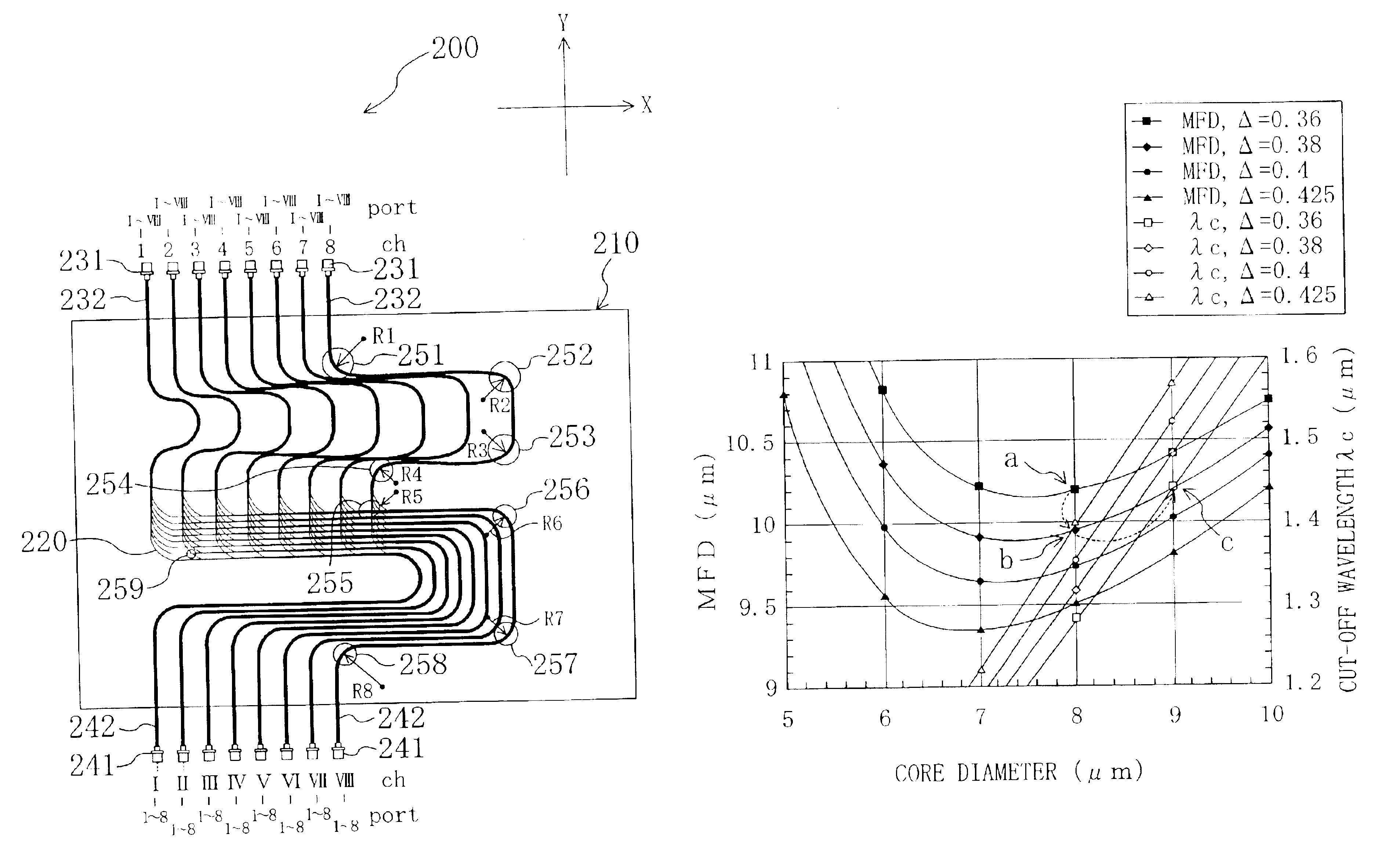
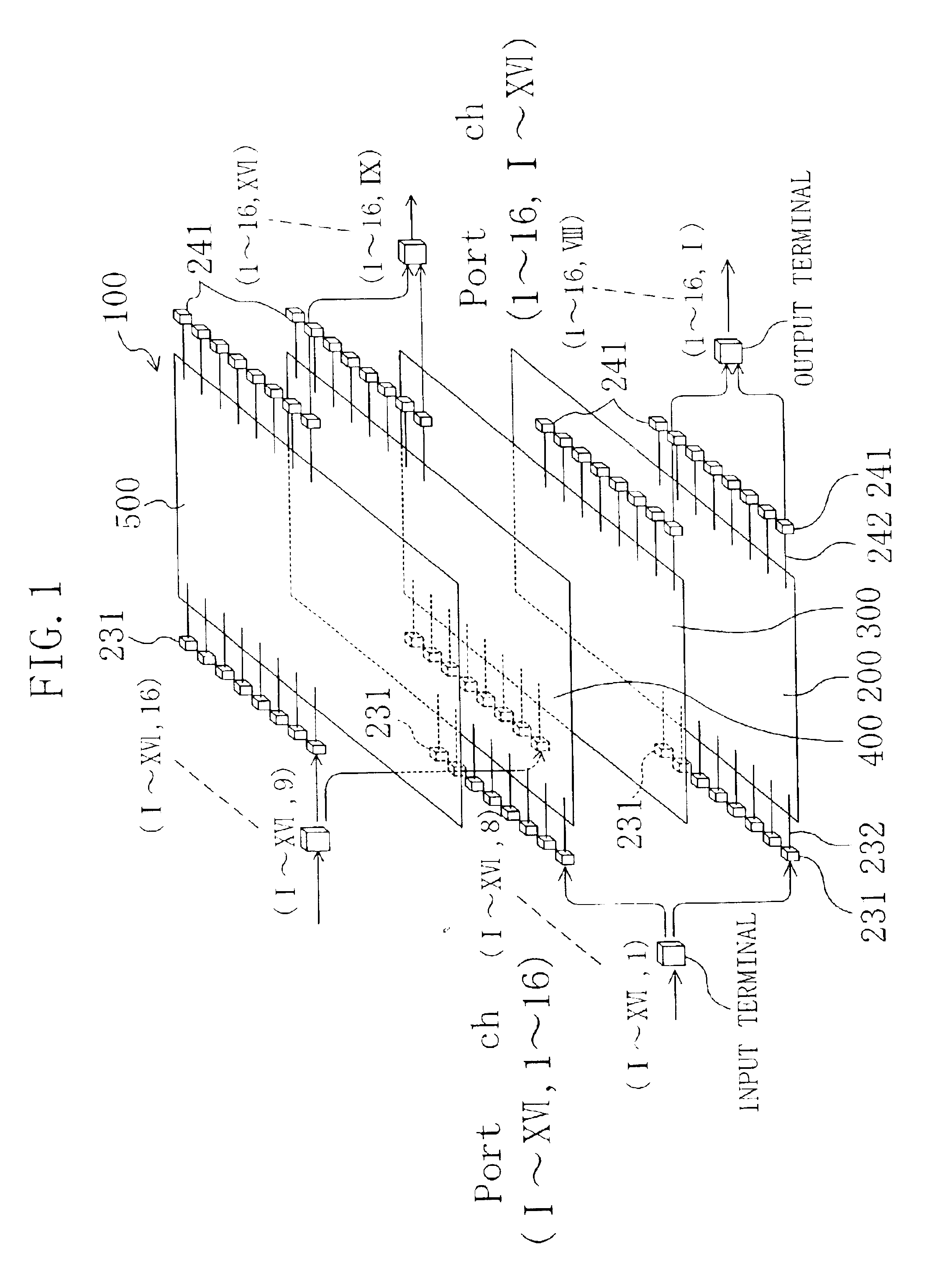
FIG. 1 shows an example of an optical matrix conversion wiring board 100 according to an embodiment of the present invention. The optical matrix conversion wiring board is an optical-fiber wiring board that converts inputs of m ports and n channels (hereinafter, referred to as "(m, n) inputs". It is noted that the letters "m" and "n" each represents a natural number) into outputs of n ports and m channels (hereinafter, referred to as "(n, m) outputs"). The optical matrix conversion wiring board 100 (hereinafter, referred to as an m.times.n optical matrix conversion wiring board) has advantages in that a number of optical fibers are arranged in units of a channel, thereby preventing erroneous wiring, and in that the optical fibers are routed on a plane, whereby a reduced storage area suffices for installation.

The optical matrix conversion wiring board 100 shown in FIG. 1 includes 16 input terminals and 16 output terminals, and it is constructed to be a 16.times.16 optical matrix conv...


PUM


Abstract

Optical fibers (220) are routed over a substrate (210), and an optical fiber wiring board (200) is thereby constructed. A relative refraction index difference Delta of the optical fiber (220) is increased to be greater than a relative refraction index difference Delta0 of a communication-dedicated single mode optical fiber, and a core diameter thereof is increased to be larger than a core diameter of the communication-dedicated optical fiber. Thereby, a mode field diameter thereof is set to be substantially the same as a mode field diameter of the communication-dedicated optical fiber.

Description

The present invention relates to an optical-fiber wiring board and an optical-fiber wiring assembly for optically interconnecting optical elements, optical circuits or optical apparatuses, and more particularly to an optimal optical fiber for the optical-fiber wiring board.Conventionally, an optical-fiber wiring board is used to optically interconnect optical elements, optical circuits or optical apparatuses. The optical-fiber wiring board is constructed to include a plurality of optical fibers routed on a substrate in a predetermined pattern. Generally, a communication-dedicated single mode optical fiber having an outside diameter of 250 .mu.m is used as an optical fiber that is routed on the optical-fiber wiring board. For example, Japanese Unexamined Patent Publication No. 2000-66035 discloses an optical fiber having an outside diameter of 125 .mu.m for an optical-fiber wiring board.In the optical-fiber wiring board, a number of portions in which the optical fibers are bent and r...

Claims


Application Information

Patent Timeline
Patent Type & Authority Patents(United States)
IPC IPC(8): G02B6/36G02B6/26G02B6/43G02B6/00G02B6/02
CPCG02B6/26G02B6/3608G02B6/43
Inventor YOSHIDA, MINORUKONDO, KATSUAKI
Owner MITSUBISHI CABLE IND LTD
Why Eureka
Try Eureka