Radial Bragg ring resonator

a ring resonator and bragging technology, applied in the field of ringlike cavities, can solve the problems of high loss, difficult to achieve these characteristics simultaneously, and small fsr, and achieve the effects of small bending radii, low loss, and large fsr

Inactive Publication Date: 2006-08-29
CALIFORNIA INST OF TECH
View PDF2 Cites 25 Cited by
  • Summary
  • Abstract
  • Description
  • Claims
  • Application Information

AI Technical Summary

Benefits of technology

[0017]The invention solves the above problems by utilizing a different method of confining the light which allows for small bending radii (and therefore large FSR) and low losses. The improved resonator structure utilizes radial Bragg reflectors in order to confine the light in a guiding defect. Unlike conventional resonators, the guiding channel could be comprised of low index material or even air, which can reduce significantly the material related loss. The utilization of radial Bragg reflectors can also reduces the bending loss of the field in the resonators (the decreases as a function of the Bragg layers number) and yet allow for small bending radii (large FSR).
[0018]The inventors have found that the utilization of Bragg reflectors as a method of confining the light to the guiding channel can decrease significantly the radiation losses of the resonator, while allowing for large FSR. The closed loop resonator waveguide of the present invention can be used in a variety of applications such as optical filters, lasers, modulators, spectrum analyzers, wavelockers, interleave filters, optical add drop multiplexers and other applications.

Problems solved by technology

However, achieving these characteristics simultaneously is difficult since the demands on the resonator shape conflict.
However, these characteristics would result in high losses which stem from three different mechanisms:Bend radiation losses;The smaller the core radius the higher the losses;Core material absorption and scattering (material loss);Surface scattering from the roughness of the core walls.
This, however, would result in a very small FSR, and also would increase overall length of the resonator and increase losses related to the material and surface roughness loss.
Hence, the current solutions cannot provide reduction of the loss of a resonator below a certain value.

Method used


Image

  • Radial Bragg ring resonator
  • Radial Bragg ring resonator
  • Radial Bragg ring resonator

Examples


Embodiment Construction

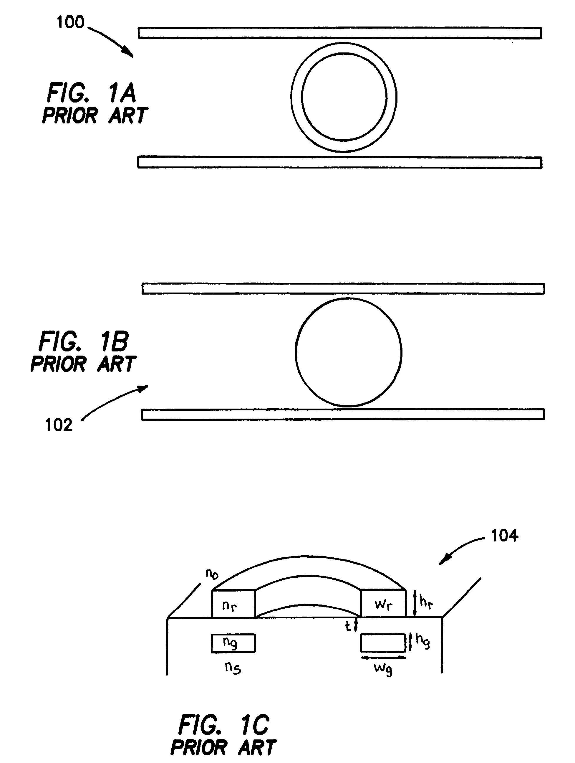
[0034]FIGS. 1A–1C are diagrams which illustrate the prior art ring resonator structure. FIGS. 1A and 1B are top plan view diagrams which show structures utilizing, respectively, a ring resonator 100 and a disk resonator 102. FIG. 1C is a perspective diagram which shows a structure utilizing circular resonator 104 and a multi-layer approach such as described in “Vertically Coupled Glass Microring Resonator Channel Dropping Filters”, B. E. Little et al., IEEE Photonics Technology Letters vol. 11 no. 2, Feb. 1999, p. 215–217.

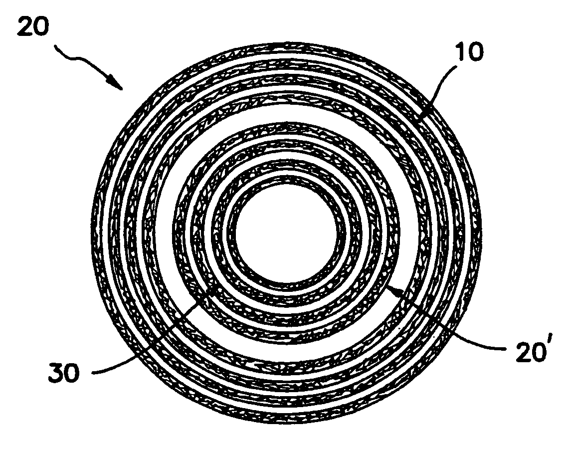
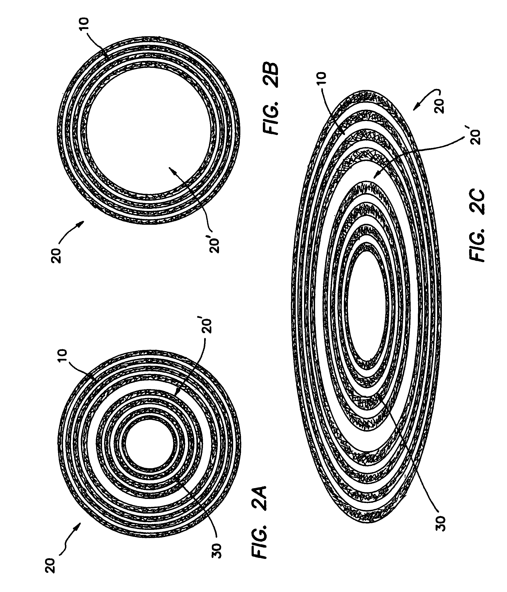
[0035]Referring to FIGS. 2A–2D, the resonator 20 according to the invention is illustrated by example in several embodiments in top plan view. In the embodiment of FIG. 2A, resonator 20 comprises a plurality of external Bragg reflectors 10, a guiding channel 20′ and a plurality of internal Bragg reflectors 30. In the embodiment of FIG. 2B, resonator 20 comprises a plurality of external Bragg reflectors 10 and a guiding core or channel 20′. In the embodiment of FIG....


PUM


Abstract

A resonator structure is presented comprising a closed loop resonator having a distributed Bragg reflector for confining the light within the guiding core. In one embodiment the light is confined from both the internal and the external sides of the device forming a guiding channel (defect) or just by the external side forming a disk resonator. Although the perfectly circular shape is generally preferred, the resonator could be of any closed loop shape such as an ellipse, etc. Although not mentioned explicitly throughout the text, the Bragg reflectors can of any type of distributed reflector such as, for example, a photonic bandgap crystal where the Bragg reflector is constructed by series of holes in a dielectric material. The resonator structure can be used in various applications, such as optical filters, lasers, modulators, spectrum analyzers, wavelockers, interleave filters, and optical add drop multiplexers.

Description

RELATED APPLICATIONS[0001]The present application is related to U.S. Provisional Patent Application Ser. No. 60 / 447,155, filed on Feb. 12, 2003, which is incorporated herein by reference and to which priority is claimed pursuant to 35 USC 119.BACKGROUND OF THE INVENTION[0002]1. Field of the Invention[0003]This invention relates to resonant optical cavities and more particularly to ring-like cavities used in integrated optical devices.[0004]2. Description of the Prior Art[0005]An optical resonator is an important element, which can be incorporated into many of the components used for optical communication systems such as lasers, filters, routers, switches, etc. Such resonator can be easily realized in integrated optical devices with linear waveguides to form a planar lightwave circuit (PLC). One of the most common roles of the optical resonator is to serve as a wavelength dependent coupler between two (or more) waveguides (input / output (I / O) waveguides). This is schematically illustr...

Claims


Application Information

Patent Timeline
Patent Type & Authority Patents(United States)
IPC IPC(8): G02B6/10G02B6/12G02B6/122G02B6/124H01S3/083H01S5/10H01S5/125
CPCB82Y20/00G02B6/12007G02B6/1225G02B6/124H01S3/083H01S5/1071H01S5/125G02B2006/1213G02B2006/12109
Inventor SCHEUER, JACOBYARIV, AMNON
Owner CALIFORNIA INST OF TECH
Why Eureka
Try Eureka