
Direct fuel injection engine

a fuel injection and engine technology, applied in the direction of machines/engines, output power, electric control, etc., can solve the problems of inability to achieve good fuel efficiency, limited engine load conditions that allow excellent stratified combustion operation, and inability to receive part of the injection

Inactive Publication Date: 2004-11-09
NISSAN MOTOR CO LTD
View PDF7 Cites 21 Cited by
  • Summary
  • Abstract
  • Description
  • Claims
  • Application Information

AI Technical Summary

Problems solved by technology

Therefore, a range of engine load conditions that allows excellent stratified combustion operation is limited with the conventional direct fuel injection engine.
More specifically, if the cavity size and other control parameter is determined to obtain stable combustion and to realize good fuel efficiency and small exhaust gas emissions during one stratified operating region with a certain engine load and a certain engine rotation speed, then good fuel efficiency may not be realized or the so-called recoil will occur in another stratified operating region with a different engine rotation speed and a different engine load.
However, in such case, the fuel stream injected during an earlier part of the injection might not be received in the cavity of the piston.
Thus, the fuel injection timing in the stratified combustion state cannot be arranged to be too early.
Accordingly, it becomes difficult to receive the fuel stream due to an insufficient depth.
Thus, since an air-fuel mixture is always formed via the cavity and ignited during stratified combustion in a conventional direct fuel injection engine, it is difficult to obtain stable combustion and good fuel efficiency as well as small exhaust emission under various conditions in which the engine rotation speed fluctuates between fast and slow.
Thus, the combustion stability is worsened thereby causing the fuel efficiency to deteriorate.
On the other hand, when the engine load is high during the stratified combustion, the air-fuel mixture in the vicinity of the spark plug tends to become excessively dense with the above mentioned conventional direct fuel injection engine.
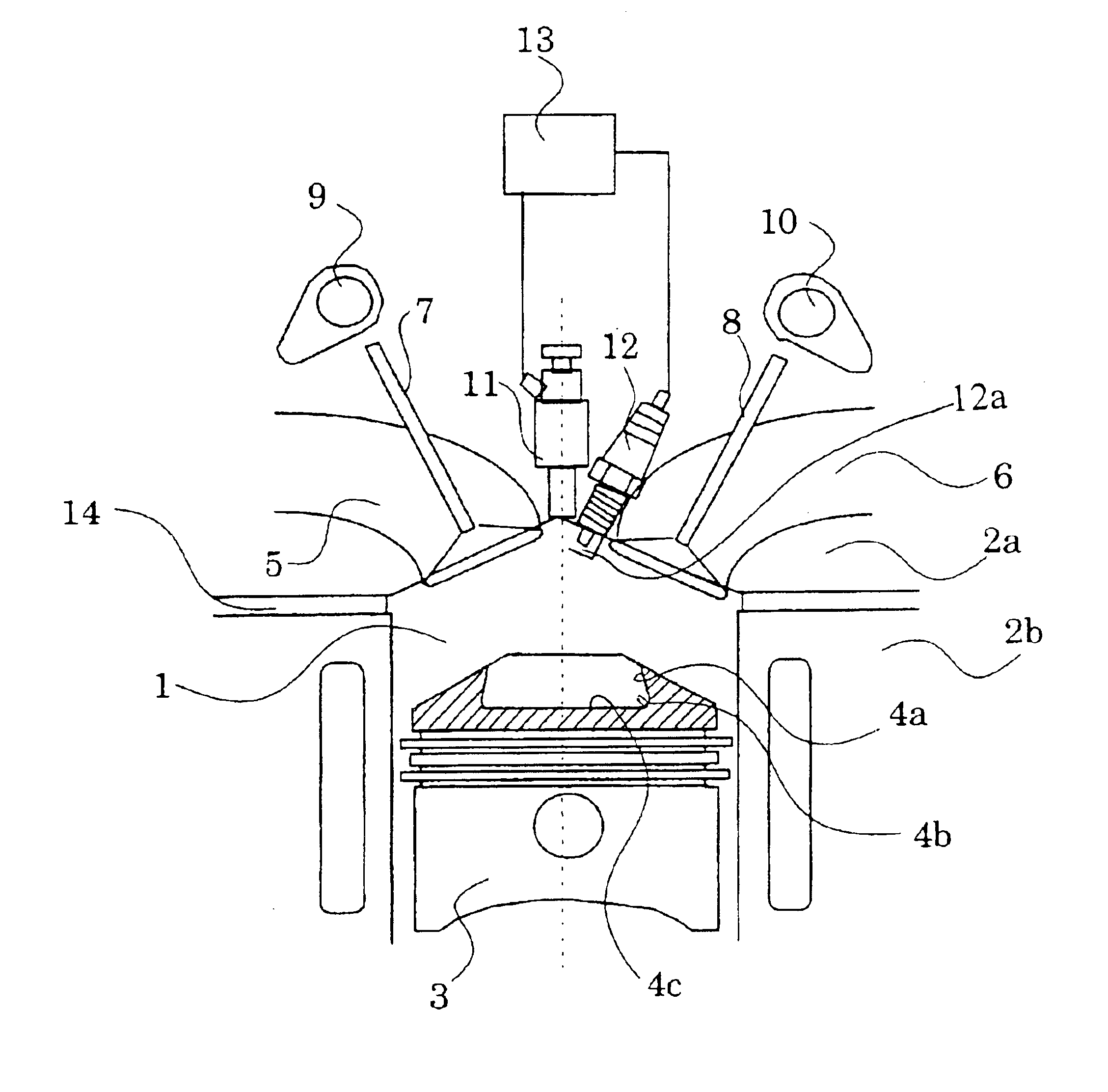
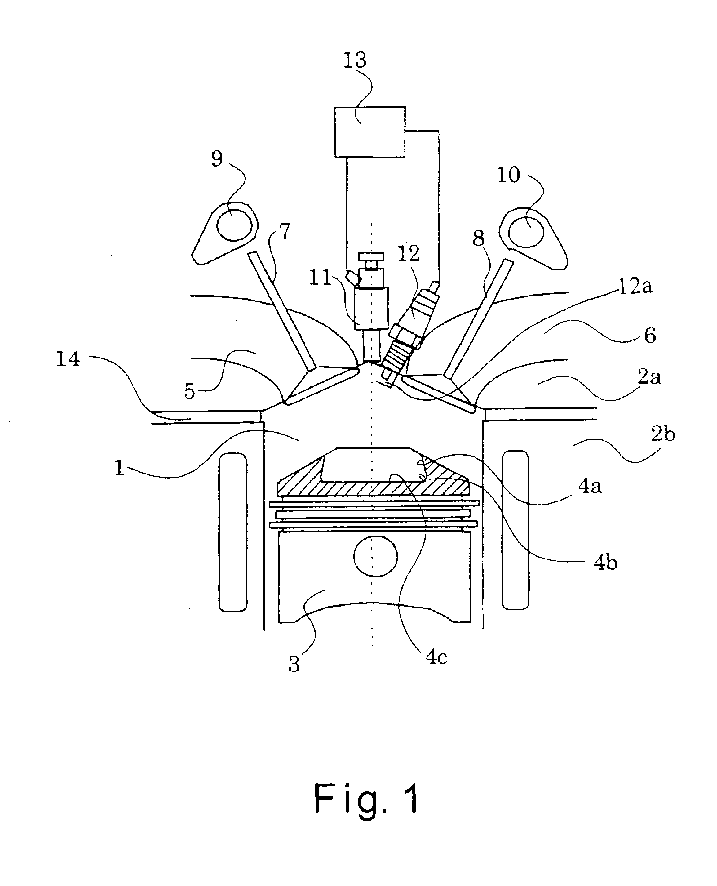
Moreover, when the engine load is low and the amount of fuel injected is small, the density of the air-fuel mixture formed by colliding the fuel stream against the piston 3 and defusing the fuel stream inside the cavity 4 generally tends to be excessively thin.

Method used


Image

  • Direct fuel injection engine
  • Direct fuel injection engine
  • Direct fuel injection engine

Examples


second embodiment

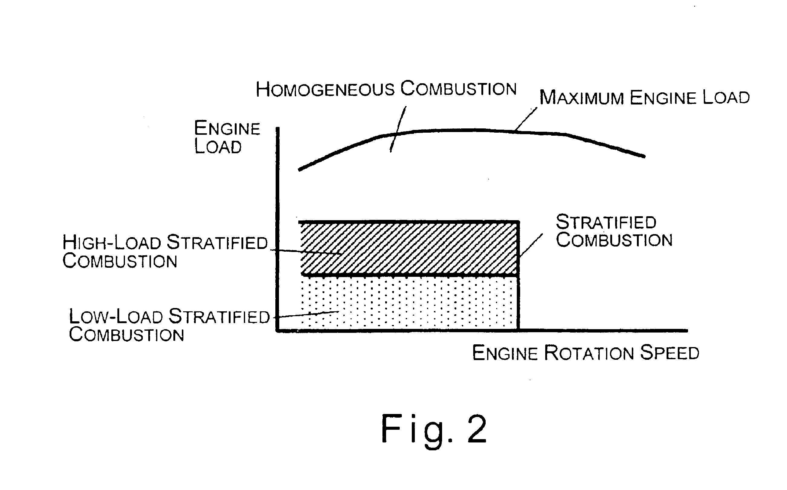
Thus, in the present invention, the operation in the low-load stratified combustion is executed when the engine rotation speed is relatively fast so that an air-fuel mixture with an air-fuel ratio suitable for ignition is always formed near the spark plug 12 regardless of the engine rotation speed. Generally, the gas flow inside the cylinder becomes larger as the engine rotation speed becomes faster. When the engine rotation speed is fast, the fuel stream is diffused and mixed with the air relatively fast due to the relatively large gas flow inside the cylinder. Thus, mixing of fuel is promoted in the flame propagation process in the low-load stratified combustion region after the fuel stream is injected due to the flow inside the cylinder when the engine rotation speed is relatively fast. Thus, the formation of an excessively dense air-fuel mixture is prevented in the low-load stratified combustion region. When, however, the engine rotation speed is relatively slow and the engine l...

third embodiment

Referring now to FIGS. 10 and 11, a direct fuel injection engine in accordance with a third embodiment will now be explained. In view of the similarity between the first and third embodiments, the parts of the third embodiment that are identical to the parts of the first embodiment will be given the same reference numerals as the parts of the first embodiment. Moreover, the descriptions of the parts of the third embodiment that are identical to the parts of the first embodiment may be omitted for the sake of brevity.

Basically, the third embodiment is identical to the first embodiment, except that an additional fuel stream is injected during the compression stroke when the direct fuel injection engine is operating in a relatively high-load region within the high-load stratified combustion region. The additional fuel stream is injected such that the additional fuel stream first hits the bottom surface 4c of the cavity 4 and guided upwardly by the curved surface 4b and the peripheral s...

fourth embodiment

Referring now to FIG. 12, a direct fuel injection engine in accordance with a fourth embodiment will now be explained. In view of the similarity between the first and fourth embodiments, the parts of the fourth embodiment that are identical to the parts of the first embodiment will be given the same reference numerals as the parts of the first embodiment. Moreover, the descriptions of the parts of the fourth embodiment that are identical to the parts of the first embodiment may be omitted for the sake of brevity. The parts of the fourth embodiment that differ from the parts of the first embodiment will be indicated with a prime (').

Basically, the fourth embodiment of the present invention is identical to the first embodiment, except that the spark plug 12 is positioned further away from the fuel injection valve 11 and a piston 3' is substituted for the piston 3 of the first embodiment. The piston 3' of the third embodiment is basically identical to the piton 3 of the first embodimen...


PUM


Abstract

A direct fuel injection engine basically comprises a combustion chamber, a piston with a cavity, a fuel injection valve, a spark plug and a control unit. The fuel injection valve is configured and arranged to directly inject a fuel stream into the combustion chamber in a substantially constant hollow circular cone shape in a stratified combustion region. The control unit is configured to ignite a first air-fuel mixture formed directly after the fuel stream is injected and prior to a majority of the fuel stream striking the cavity when the direct fuel injection engine is operating in a low-load stratified combustion region, and to ignite a second air-fuel mixture formed after a majority of the fuel stream is guided by the cavity toward an upper portion of the combustion chamber above the cavity when the direct fuel injection engine is operating in a high-load stratified combustion region.

Description

1. Field of the InventionThe present invention generally relates to a direct fuel injection engine in which a fuel is directly injected in a combustion chamber and ignited by a spark plug. More specifically, the present invention relates to a direct fuel injection engine that performs stratified combustion and homogeneous combustion by directly injecting a fuel in the combustion chamber.2. Background InformationOne example of a conventional direct fuel injection engine is disclosed in Japanese Laid-Open Patent Publication No. H11-82028. The direct fuel injection engine disclosed in this reference has a concave cavity or a piston bowl formed on the piston crown surface. In addition, this conventional direct fuel combustion engine forms a suitable stratified air-fuel mixture in the cylinder by arranging a fuel injection valve substantially directly above the piston bowl. This arrangement allows the fuel stream to collide against a peripheral side wall of the piston bowl and form a fue...

Claims


Application Information

Patent Timeline
IPC IPC(8): F02D37/02F02D37/00F02B23/10F02D13/02F02D41/40F02D41/30F02B17/00F02B75/12F02B75/00
CPCF02B17/005F02D13/0215F02D37/02F02D41/3023F02D41/401F02B23/101Y02T10/123F02B2075/125F02B2275/18F02D41/3029F02D2041/001Y02T10/12Y02T10/125Y02T10/18Y02T10/44Y02T10/40
Inventor HIRAYA, KOJITAKAHASHI, EIJITSUCHIDA, HIROFUMIHOTTA, ISAMUKAKUHO, AKIHIKO
Owner NISSAN MOTOR CO LTD
Learn More