Accumulation type fuel injection system
a fuel injection system and accumulation type technology, applied in the direction of liquid fuel feeders, machines/engines, electric control, etc., can solve the problems of noise generation in combustion, supply pump no function to actively and supply pump has no function to reduce the pressure of common rail
- Summary
- Abstract
- Description
- Claims
- Application Information
AI Technical Summary
Benefits of technology
Problems solved by technology
Method used
Image
Examples
first embodiment
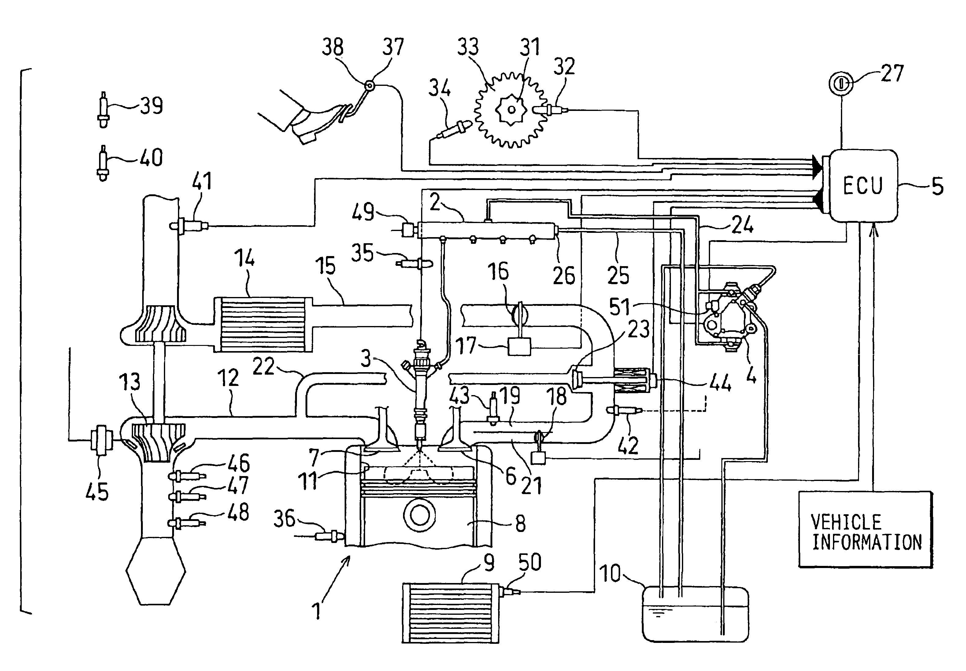
Referring to FIG. 1, an accumulation type fuel injection system according to the first embodiment of the present invention is illustrated. As shown in FIG. 1, the accumulation type fuel injection system of the present embodiment is a system for injecting fuel into an internal combustion engine (an engine, hereafter) 1 such as a four-cylinder diesel engine. The accumulation type fuel injection system has a common rail 2, injectors 3, a supply pump 4, an engine control unit (ECU) 5, and the like. The common rail 2 is a high-pressure vessel for accumulating the fuel at a high pressure corresponding to a fuel injection pressure. The injectors 3 inject the fuel accumulated in the common rail 2 into respective cylinders of the engine 1. The supply pump 4 pressurizes drawn fuel and pressure-feeds the high-pressure fuel to the common rail 2. The ECU 5 corresponds to a control device for electronically controlling the injectors 3 and the supply pump 4 in accordance with an operating state of...
second embodiment
Next, an accumulation type fuel injection system according to the second embodiment will be explained based on FIGS. 7 and 8.
Combustion slackening means of the second embodiment slackens the combustion by setting the injection mode to the multi-step injection mode (the pilot injection mode or the multi-injection mode) so that the injection quantity of the minute injection is increased from the injection quantity of the minute injection in the normal injection mode as shown by a solid line Qp1 and a broken line Qp2 in FIG. 7A. The solid line Qp1 in FIG. 7A represents an injection ratio in the normal injection mode. The broken line Qp2 in FIG. 7A represents an injection ratio in the corrected injection mode. The main injection quantity is decreased by the increase in the injection quantity of the minute injection as shown in FIG. 7A.
The combustion slackening means of the present embodiment increases the injection quantity of the minute injection as the pressure difference .DELTA.P pro...
third embodiment
Next, an accumulation type fuel injection system according to the third embodiment of the present invention will be explained based on FIGS. 9 and 10.
Combustion slackening means of the third embodiment slackens the combustion by performing the minute injection and the main injection in one injection period through the injector 3 and by lengthening an interval INT between the injections in one injection period as shown by broken lines in FIG. 9A from a normal injection interval shown by solid lines in FIG. 9B.
The combustion slackening means of the present embodiment lengthens the injection interval INT in one injection period as the pressure difference .DELTA.P provided by subtracting the target pressure Pfin from the actual pressure NPC increases. More specifically, the combustion slackening means calculates a correction coefficient K corresponding to the pressure difference .DELTA.P with a formula or a map and increases the injection interval INT by multiplying the value of the inj...
PUM
 Abstract
Description
Claims
Application Information
 - R&D
- Intellectual Property
- Life Sciences
- Materials
- Tech Scout
- Unparalleled Data Quality
- Higher Quality Content
- 60% Fewer Hallucinations
Browse by: Latest US Patents, China's latest patents, Technical Efficacy Thesaurus, Application Domain, Technology Topic, Popular Technical Reports.
© 2025 PatSnap. All rights reserved.Legal|Privacy policy|Modern Slavery Act Transparency Statement|Sitemap|About US| Contact US: help@patsnap.com


