Connecting device

a technology of connecting device and connecting rod, which is applied in the direction of connecting rod, rope and cable for vehicles/pulleys, bridges, etc., can solve the problems of high cost, long assembly and dismantling time, and awkward handling

Inactive Publication Date: 2004-11-09
VSL INT AG
View PDF9 Cites 16 Cited by
  • Summary
  • Abstract
  • Description
  • Claims
  • Application Information

AI Technical Summary

Problems solved by technology

Known wire locks generally suffer from the disadvantage that they are awkward to handle and take a long time to assemble and dismantle, which results in high costs.
They also have a tendency to come unscrewed and/or to nip the wire core, which makes dismantling of the casing body more difficult.
Nipping of the various parts in known wire locks furthermore means that they sit so tight fast after drawing of the wire that the devices must be scrapped, which results in high costs and unnecessarily high material consumption.
Known systems suffer therefore from lack of flexibility, primarily w...

Method used


Image

  • Connecting device
  • Connecting device
  • Connecting device

Examples


first embodiment

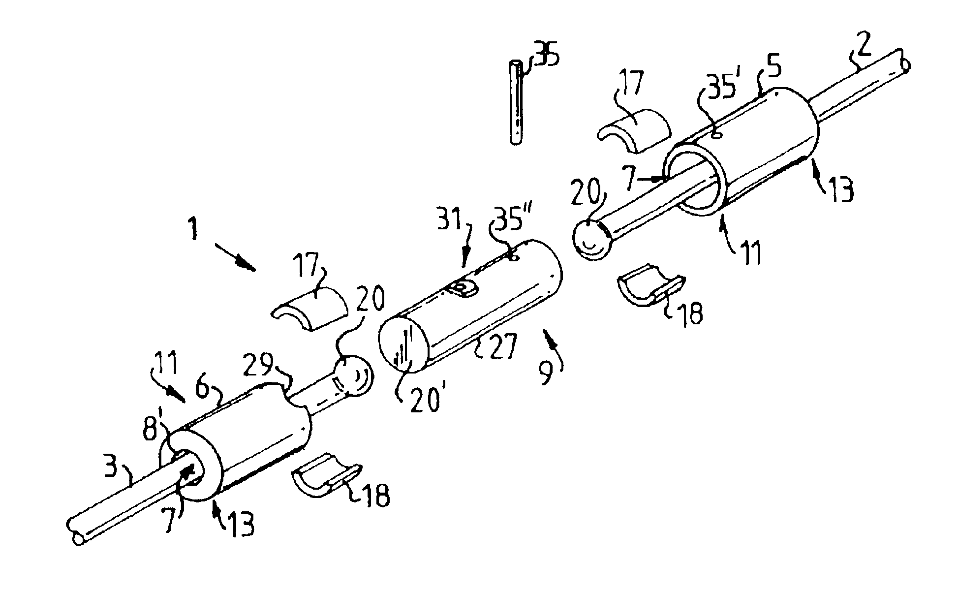
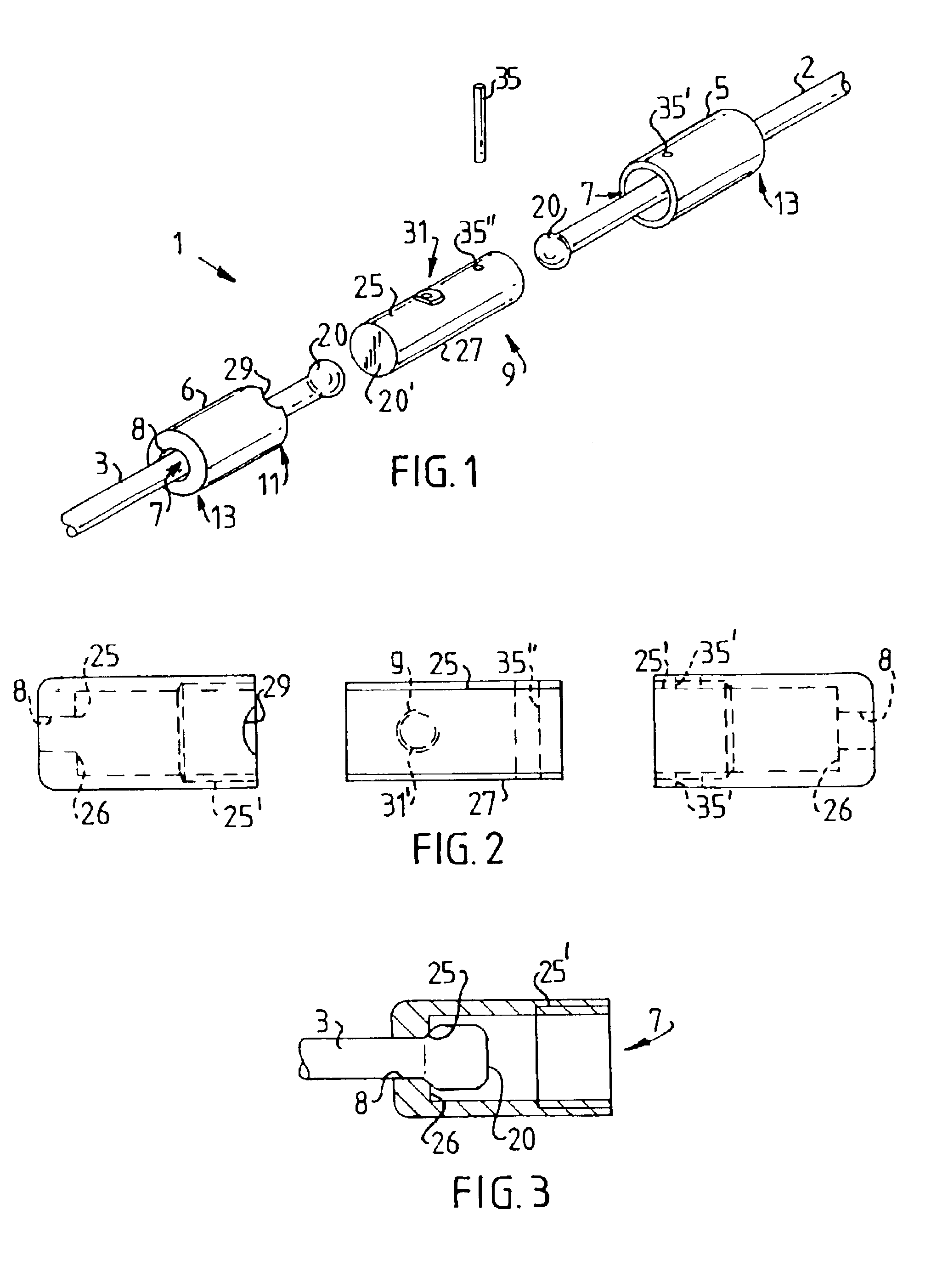
The term "working position" is taken to mean the condition in which the joint casing is fitted and locked between two wire ends. FIG. 1 shows a connecting element 1 according to the invention in a dismantled condition. The connecting element 1 in FIG. 1 is intended to connect a draw wire 2 to a bracing wire 3. The connecting element 1 comprises a first and a second casing body 5 and 6, of which the first casing body 5 is intended to be coupled to the draw wire 2, which during construction is intended to draw a number of bracing wires 3 one at a time into a cable duct (not shown in FIG. 1, shown as 56 in FIG. 9). When the draw wire 2 has been passed through the first casing body 5 the end of the draw wire is upset to form a boss 20. The boss 20 can thus be made of the same material as the bracing wire 3. This has the advantage that there does not need to be any further material on the construction site in order to produce the boss 20. Upsetting is advantageously performed with a roun...

second embodiment

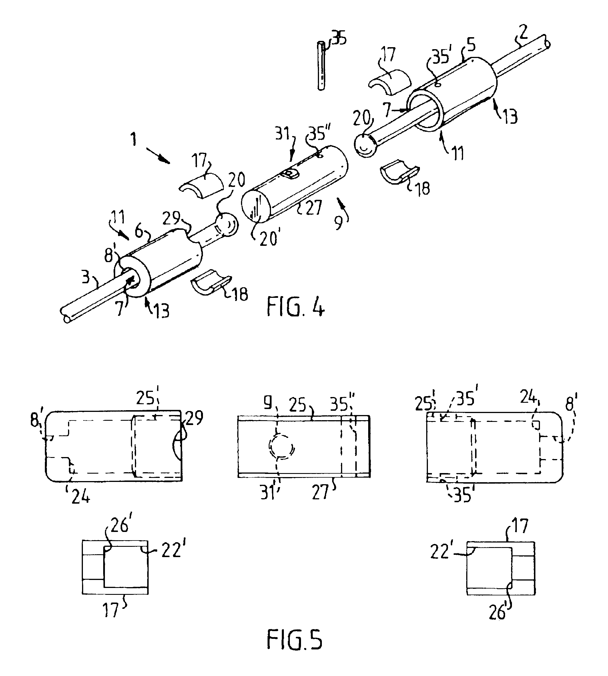
FIG. 6 shows a diagram of a connecting element 1 fitted to a bracing wire 3 and a draw wire 2. The reference numbers occurring in FIGS. 6 and 7 correspond to the reference numbers described and shown earlier, but it must be noted that the connecting element is viewed from a different direction to that shown in FIGS. 3-5. FIG. 6 clearly shows how the bracing wire 3 and the draw wire 2 bear against respective projections 17 and 18 (only 17 is shown in FIGS. 6 and 7, because 18 is obscured). The projections 17 and 18 in turn bear against a shoulder 24.

In the working position the bosses 20 produced at each wire end bear, freely rotatable, against the casing body 5 and 6 by way of the projections 17 and 18, producing an axial locking of each wire end. The number of parts has thus been substantially reduced compared to the prior art, which gives greater operating reliability. Because the wire core or the connecting element is free to rotate, undesirable stresses in the wire are avoided. ...


PUM


Abstract

Connecting element for joining two support members (2, 3) absorbing tensile forces, which connecting element (1) comprises at least a first and a second casing body (5, 6) with a through-hole (7) for receiving the respective support members (2, 3), which casing bodies (5, 6) can be joined together by way of a joining section (9) at a first end (11) of each casing body (5, 6), the opposing second end (13) of each casing body (5, 6) being provided with locking members (15, 16) for holding the support members (2, 3) fast. In a working position the locking member (15, 16) of at least one casing body (5, 6) produces an axial locking of the support member (2, 3) running through the casing body (5, 6) by way of a stop part (20) created on the support member (2, 3) within the area of the second end (13) of the casing body (5, 6).

Description

The present invention relates to a connecting element for joining two support members absorbing tensile forces, which connecting element comprises at least a first and a second casing body with a through-hole for receiving the respective support members, which casing bodies can be joined together by way of a joining section at a first end of each casing body, the opposing second end of each casing body being provided with locking members for holding the support members fast.BACKGROUND OF THE ARTThe invention has applications in the construction industry but is not confined to this. Connecting elements, or so-called wire locks, are used for joining support members, such as wire cores in bracing wires, together. Joining can be done during the actual process of assembling a cable consisting of a number of such bracing wires, where tightening of each bracing wire is done separately.When the wire is tensioned with the required force, the wire can be permanently locked by means of a wedge...

Claims


Application Information

Patent Timeline
IPC IPC(8): F16G11/00F16G11/08E01D11/04E01D11/00E01D19/16E04B1/58
CPCF16G11/08Y10T403/5733Y10T403/5773Y10T403/5753Y10T403/5741Y10T403/5746Y10T403/5713Y10T403/5781F16G11/12
Inventor NILSSON, IVAR
Owner VSL INT AG
Why Eureka
Try Eureka