Multiple bandwidth phase lock filters for multimode radios

a multi-bandband, phase lock technology, applied in the direction of multiple-port networks, pulse automatic control, line-transmission details, etc., can solve the problems of increasing the size, cost and overall design efficiency of the transceiver

Inactive Publication Date: 2004-11-16
QUALCOMM INC
View PDF13 Cites 42 Cited by
  • Summary
  • Abstract
  • Description
  • Claims
  • Application Information

AI Technical Summary

Problems solved by technology

A conventional design would include two separate PLL circuits and switch between them as necessary, however such an approach increases the size, cost and overall design efficiency of the transceiver.

Method used


Image

  • Multiple bandwidth phase lock filters for multimode radios
  • Multiple bandwidth phase lock filters for multimode radios
  • Multiple bandwidth phase lock filters for multimode radios

Examples


fourth embodiment

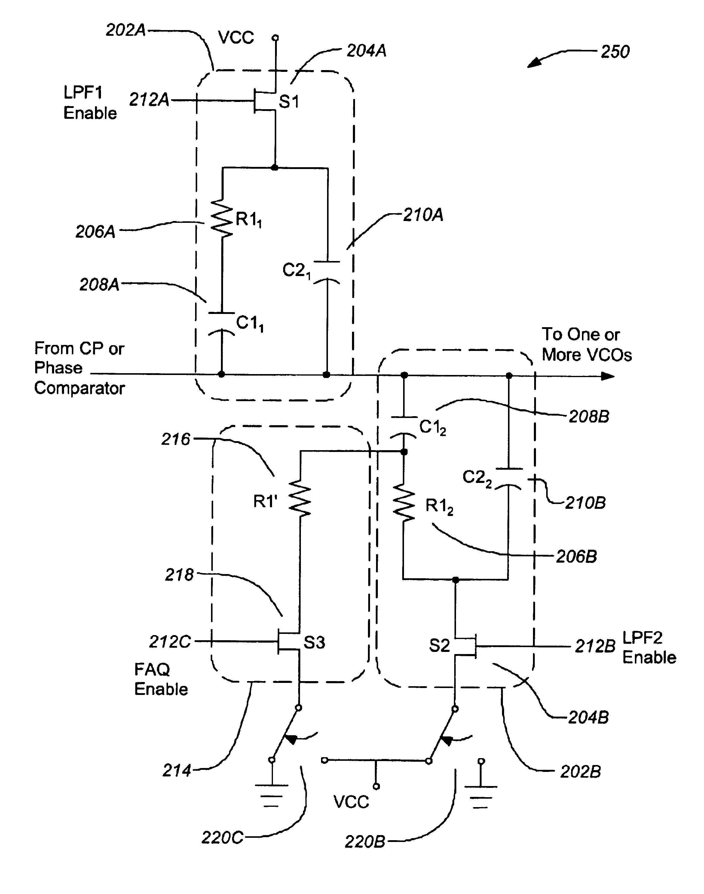
FIGS. 4A and 4B are a circuit 400 and control matrix for the invention. FIG. 4A is a circuit diagram of filter circuit 400. This filter embodiment is designed with a first filter subcircuit 402A and a second filter subcircuit 402B merged in a manner similar to the third filter embodiment above. The first filter subcircuit 402A and the second filter subcircuit 402B share common filter circuit elements.

FIG. 4B is a table showing the switch combinations of the fourth filter 400 embodiment. In this filter circuit 400, selection of the first or second filter subcircuit 402A, 402B is not effected by activating one switch and deactivating another switch as in the previous embodiments. To enable the first filter subcircuit 402A, the first and second enable switches 404A, 404B are both activated in a first switch combination. To enable the second filter subcircuit 402B, the first and second enable switches 404A, 404B are both deactivated in a second switch combination. Here also, the first a...

embodiment

3. Example Method Embodiment

FIG. 5 is a flowchart 500 illustrating a method of filtering a phase error signal according to the invention. The method begins by receiving a phase error signal from a phase comparator at block 502. The phase error signal is filtered with a first filter subcircuit when a first enable switch is activated at block 504. The phase error signal is filtered with a second filter subcircuit when a second enable switch is activated at block 506. Optionally, the error signal may be fast acquisitiond by a fast acquisition subcircuit while at least one of the first and second filter subcircuits are filtering the error signal when a third enable switch is activated at block 508. Such fast acquisition may be temporarily enabled to improve the overall performance of the PLL circuit.


PUM


Abstract

An apparatus and method for filtering a signal in a phase lock loop is disclosed. An typical apparatus for filtering a phase error signal comprises a first filter subcircuit receiving a phase error signal from a phase comparator and filtering the error signal when enabled, a second filter subcircuit receiving the phase error signal from the phase comparator and filtering the error signal when enabled and first and second enable switches which are activated in combination to control filtering of at the error signal. The first filter subcircuit is enabled by activating a first combination of the enable switches and the second filter subcircuit is enabled by activating a second combination of the enable switches. A fast acquisition subcircuit can also be used to temporarily underdampen the filter and improve overall performance of the phase lock loop circuit. The filter can be used to obtain multimode operation in a cellular radio.

Description

1. Field of the InventionThe present invention relates to systems and methods for implementing phase lock loop (PLL) circuits in multimode radios, and particularly for implementing PLL circuits in multimode code division multiple access (CDMA) cellular radios that include global positioning system (GPS) receivers and other global systems for mobile communications (GSM) technologies.2. Description of the Related ArtPhase Locked Loop (PLL) circuits are well known and used for frequency control in a variety of applications. For example, they can be configured as frequency multipliers, demodulators, tracking generators or clock recovery circuits. Each of these applications may demand different characteristics, however they all use the same basic circuit concept.FIG. 1A illustrates a block diagram of a conventional PLL circuit 100. The operation of this circuit 100 is typical of all phase locked loops. It is basically a feedback control system that controls the phase of a voltage control...

Claims


Application Information

Patent Timeline
Patent Type & Authority Patents(United States)
IPC IPC(8): H03L7/093H03L7/089H03L7/107H03L7/08H03L7/18H03L7/16
CPCH03L7/0898H03L7/107H03L7/093H03L7/18H03L7/1072H03L2207/06
Inventor MALDONADO, DAVID
Owner QUALCOMM INC
Why Eureka
Try Eureka