Integrated component mounting system for use in an X-ray tube

a technology for mounting systems and components, applied in the direction of x-ray tube electrodes, electrical devices, electric discharge tubes, etc., can solve the problems of high operating temperature of the target anode, significant amount of heat produced in the target anode, and difficult positioning of the component, so as to facilitate the centering of the component. , the effect of facilitating the positioning of the componen

Inactive Publication Date: 2004-11-16
VARIAN MEDICAL SYSTEMS
View PDF19 Cites 16 Cited by
  • Summary
  • Abstract
  • Description
  • Claims
  • Application Information

AI Technical Summary

Benefits of technology

Briefly summarized, embodiments of the present invention provide an integrate component mounting system that facilitates radial positioning of the component, relative to a shaft to which the component is mounted, as well as the maintenance of a desired radial and axial position of the component.
Embodiments of the present invention are particularly well suited for use in rotating anode type x-ray tubes. However, embodiments of the present invention are suitable for use in any application or environment where it is useful to establish and maintain a desired lateral and axial position of a shaft mounted component and thereby reduce the noise, vibration, and the other undesirable effects associated with unbalanced and inadequately secured components.
As the nut is tightened and comes into contact with the component, the shaped surfaces cooperate in such a way that radial and axial forces are simultaneously applied to the component. The axial force serves to facilitate positioning of the component against the support member of the shaft, while the radial force facilitates the centering of the component with respect to the shaft.
In this way, the shaped surfaces cooperate with each other to insure that, regardless of the initial orientation of the component on the shaft, the component will be centered on the shaft, and securely positioned against the support member, upon completion of the tightening of the nut. Further, the axial force exerted as a result of the cooperation of the shaped surfaces acts to substantially foreclose radial runout of the component during operation and thereby helps prevent unbalanced rotary motion of the component.

Problems solved by technology

Due to the nature of the operation of an x-ray tube, components of the x-ray tube are subjected to a variety of demanding operating conditions.
For example, in addition to stimulating the production of x-rays, the kinetic energy of the striking electron stream also causes a significant amount of heat to be produced in the target anode.
As a result, the target anode typically experiences extremely high operating temperatures, as high as 2300.degree. C. during normal operations.
In addition to experiencing high operating temperatures, the components of the x-ray device are also exposed to thermal stress cycling situations where relatively wide variations in operating temperature may occur in a relatively short period of time.
The relatively rapid rate at which such temperature changes take place imposes high levels of thermally-induced stress and strain in the x-ray tube components.
Further, many of the rotating components of a typical rotating anode type x-ray device are additionally subjected to high levels of non-thermally induced mechanical stress induced by high speed rotation of the anode and shaft.
This high rate of acceleration imposes significant mechanical stresses on the anode, the shaft and the nut.
Thus, the components which are used to secure the anode in position are exposed not only to extreme thermal stresses, but are simultaneously exposed to significant stresses imposed by the mechanical operations of the x-ray device.
The operating conditions just described have a variety of effects that may be detrimental to the operation and service life of the x-ray tube.
However, while such a gap may be useful in the sense that it permits initial positioning of the anode with respect to the shaft, the gap also allows the possibility of undesirable lateral movement, or radial runout, of the anode when the anode is subjected to mechanical and thermal stresses.
Failure to compensate for, or otherwise eliminate, such radial runout by limiting or preventing the movement of the target anode may cause problems with the operation of the device.
For example, high operational speeds and mechanical stresses may cause a target anode that is relatively unconstrained from radial movement to vibrate and produce noise during operation of the x-ray device.
Such vibration and noise, in turn, have various negative consequences with respect to the performance and operational life of the x-ray device.
Because high quality imaging depends upon reliable maintenance of focal spot positioning, any such focal spot movement will compromise the quality of the images that can be produced with the x-ray device.
Furthermore, unchecked vibration may ultimately damage the target anode, shaft, the nut, or other components of the x-ray device.
Moreover, noise and vibration may be unsettling to the x-ray device operator and the x-ray subject, particularly in mammographic applications where the subject is in relatively intimate contact with the x-ray device.

Method used


Image

  • Integrated component mounting system for use in an X-ray tube
  • Integrated component mounting system for use in an X-ray tube
  • Integrated component mounting system for use in an X-ray tube

Examples


Embodiment Construction

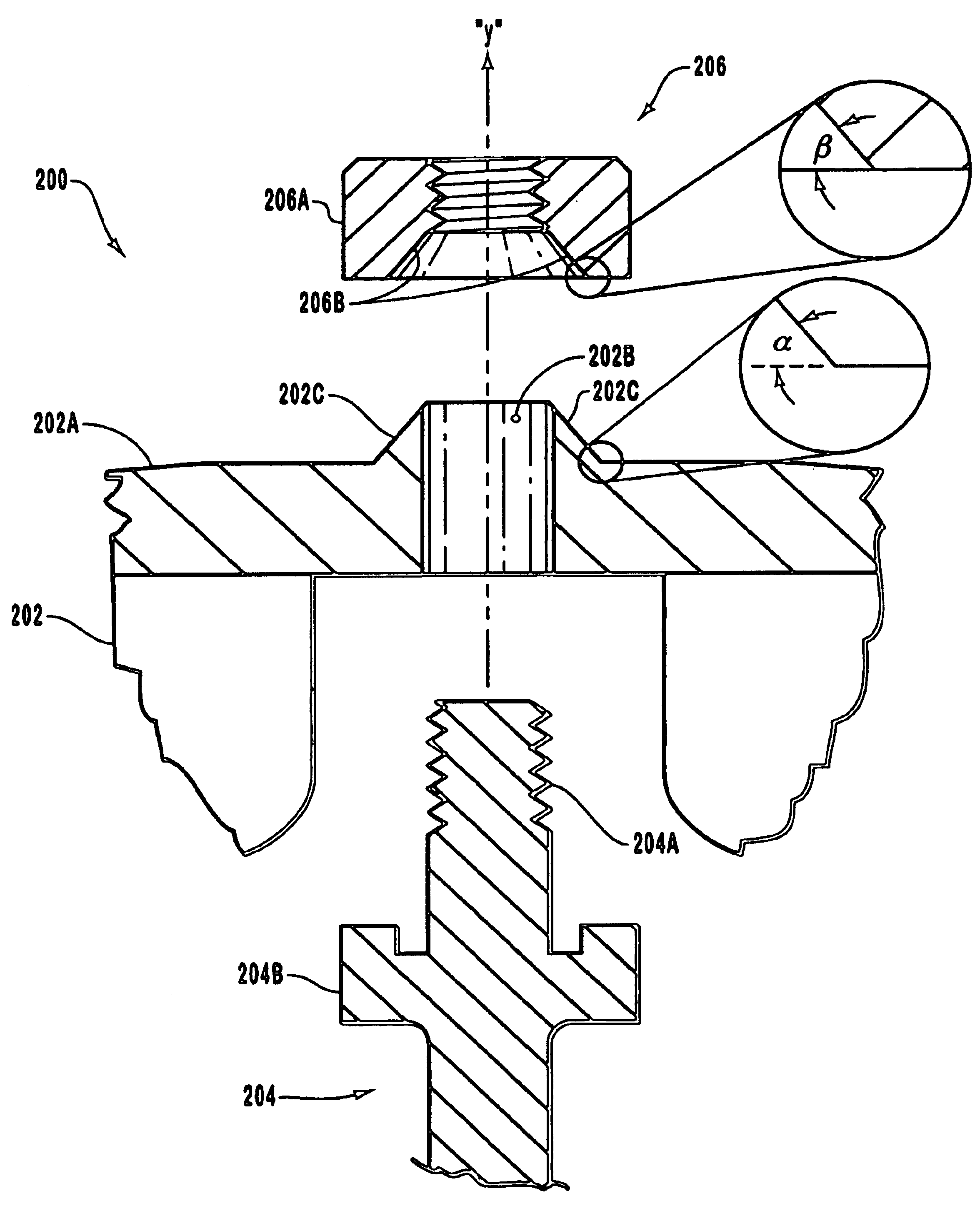
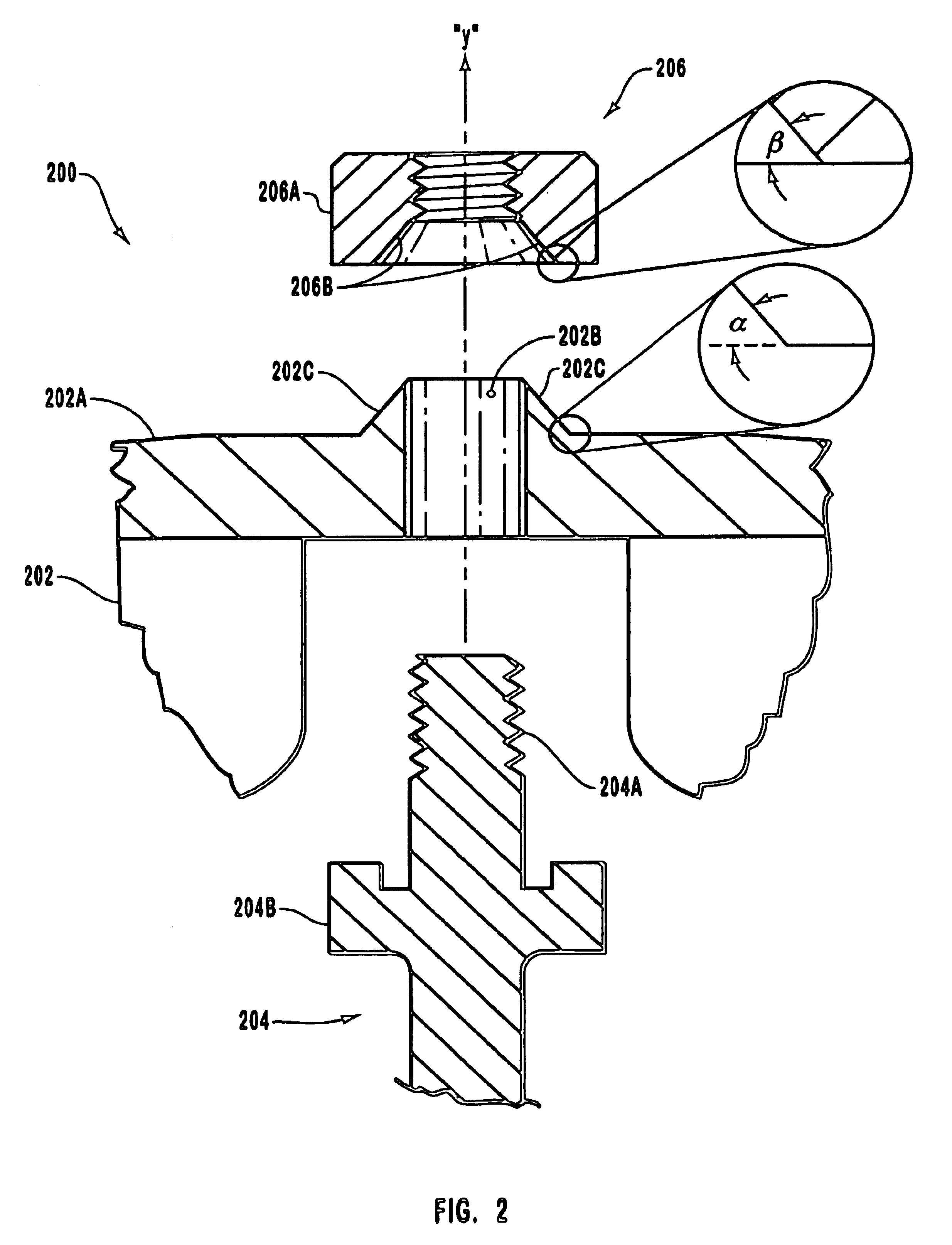
Reference will now be made to figures wherein like structures will be provided with like reference designations. It is to be understood that the drawings are diagrammatic and schematic representations of various embodiments of the invention, and are not to be construed as limiting the present invention, nor are the drawings necessarily drawn to scale.

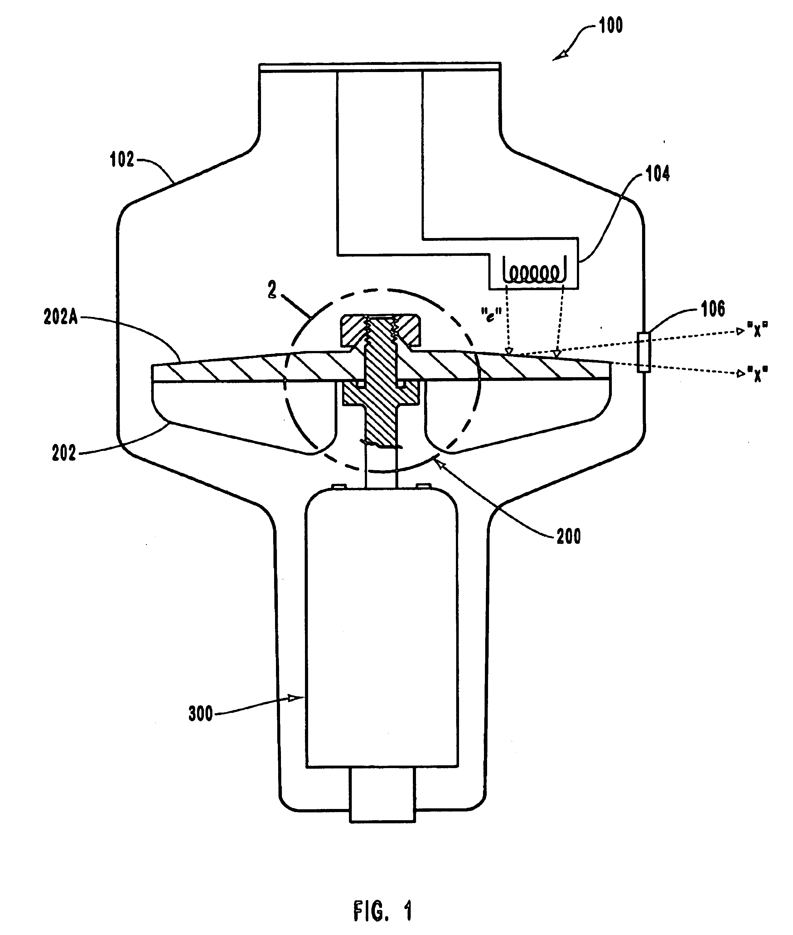
Reference is first made to FIG. 1, wherein an x-ray tube is indicated generally at 100. Note that x-ray tube 100 is simply an exemplary operating environment for embodiments of the present invention and that such embodiments may profitably be employed in any other environment where it is desired to implement the functionality disclosed herein. By way of example, some embodiments of the invention may be used in conjunction with components such as pump impellers.

As indicated in the illustrated embodiment, x-ray tube 100 includes a vacuum enclosure 102, inside which is disposed an electron source 104, such as a cathode. An integrated compo...


PUM

PropertyMeasurementUnit
operating temperaturesaaaaaaaaaa
temperatureaaaaaaaaaa
radial forceaaaaaaaaaa

Abstract

An integrated component mounting system that includes a component mounted to a shaft and secured in place by a nut. The component and the nut each define respective annular shaped surfaces. The shaped surfaces are each inclined at a similar angle and are arranged for sliding contact with respect to each other. As the nut is tightened on the shaft, the shaped surface of the nut exerts both radial and axial forces on the shaped surface of the component, thereby automatically centering the component radially on the shaft as well as securing the component at a desired location along the shaft.

Description

1. The Field of the InventionThe present invention relates generally to mounting systems for positioning and securing a component on a shaft. More particularly, embodiments of the present invention relate to target anode mounting systems and devices that include various features which serve to reliably and effectively establish and maintain the both the axial and radial position of the target anode in a variety of operating conditions.2. Related TechnologyX-ray producing devices are valuable tools that are used in a wide variety of industrial, medical, and other applications. For example, such equipment is commonly used in areas such as diagnostic and therapeutic radiology, semiconductor manufacture and fabrication, and materials analysis and testing. While they are used in various different applications, the different x-ray devices share the same underlying operational principles. In general, x-rays, or x-ray radiation, are produced when electrons are produced, accelerated, and the...

Claims


Application Information

Patent Timeline
Patent Type & Authority Patents(United States)
IPC IPC(8): H01J35/10H01J35/00
CPCH01J35/101Y10T29/53
Inventor MILLER, ROBERT STEVEN
Owner VARIAN MEDICAL SYSTEMS
Why Eureka
Try Eureka