
Method for repairing articles of ceramic composites

a technology of ceramic composites and repair methods, applied in the direction of sustainable transportation, mechanical equipment, machines/engines, etc., can solve the problem of quite expensive cmcs

Inactive Publication Date: 2004-11-23
GENERAL ELECTRIC CO
View PDF20 Cites 65 Cited by
  • Summary
  • Abstract
  • Description
  • Claims
  • Application Information

AI Technical Summary

Benefits of technology

In service, gas turbine components operate at temperatures frequently exceeding 1200.degree. C. and are subjected to significant temperature gradients. In addition, these components are exposed to impact loading from particles having high velocity that are entrained in the hot gases. The severe service conditions render these components prone to various types of damage. Large thermal gradients can initiate cracks at component edges or joint areas. Damages by foreign objects such as high-speed entrained particles can result in holes, indentations, or cracks that can propagate. The method of the present invention for repairing damages in gas turbine engine components made of CMCs can extend the life of these components. In addition, the method of the present invention can repair damages in newly-manufactured components and, thus, reduce the number of defective or off-specification components. The method of the present invention provides repaired components that exhibit toughness behavior similar to newly-manufactured defect-free components.
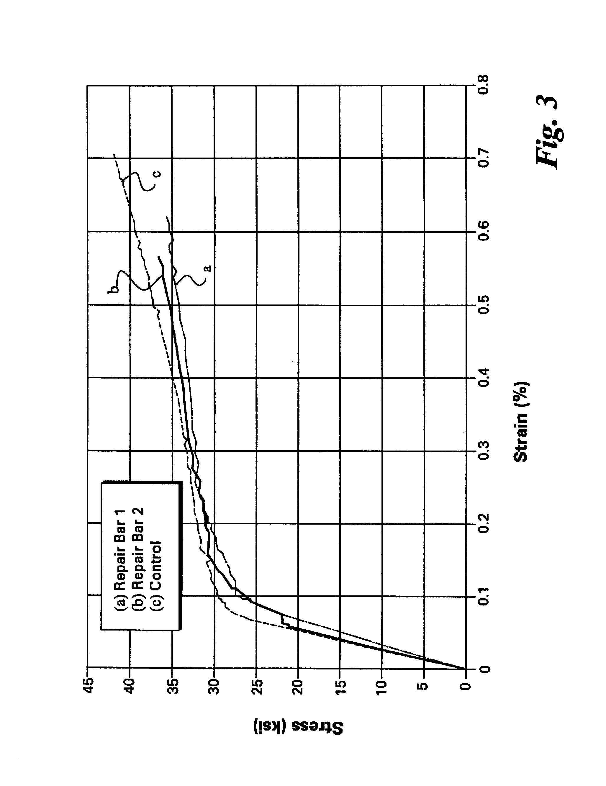
CMC articles that were repaired using the method of the present invention showed toughness behavior similar to that of the defect free articles characterized by a rising stress-strain curve past the initial matrix cracking point. In other words, the CMC articles repaired according to the method of the present invention did not fail catastrophically.

Problems solved by technology

CMCs are quite expensive because their typical production process is rather involved.

Method used


Image

  • Method for repairing articles of ceramic composites
  • Method for repairing articles of ceramic composites
  • Method for repairing articles of ceramic composites

Examples


example 2

Repair by Applying an External Patch of Hi-Nicalon.TM. Fiber-Reinforced Prepreg Tape to a Melt-Infiltrated Slurry Cast Si--SiC Matrix Composite Reinforced with Tyranno-ZMI.TM. SiC Fibers

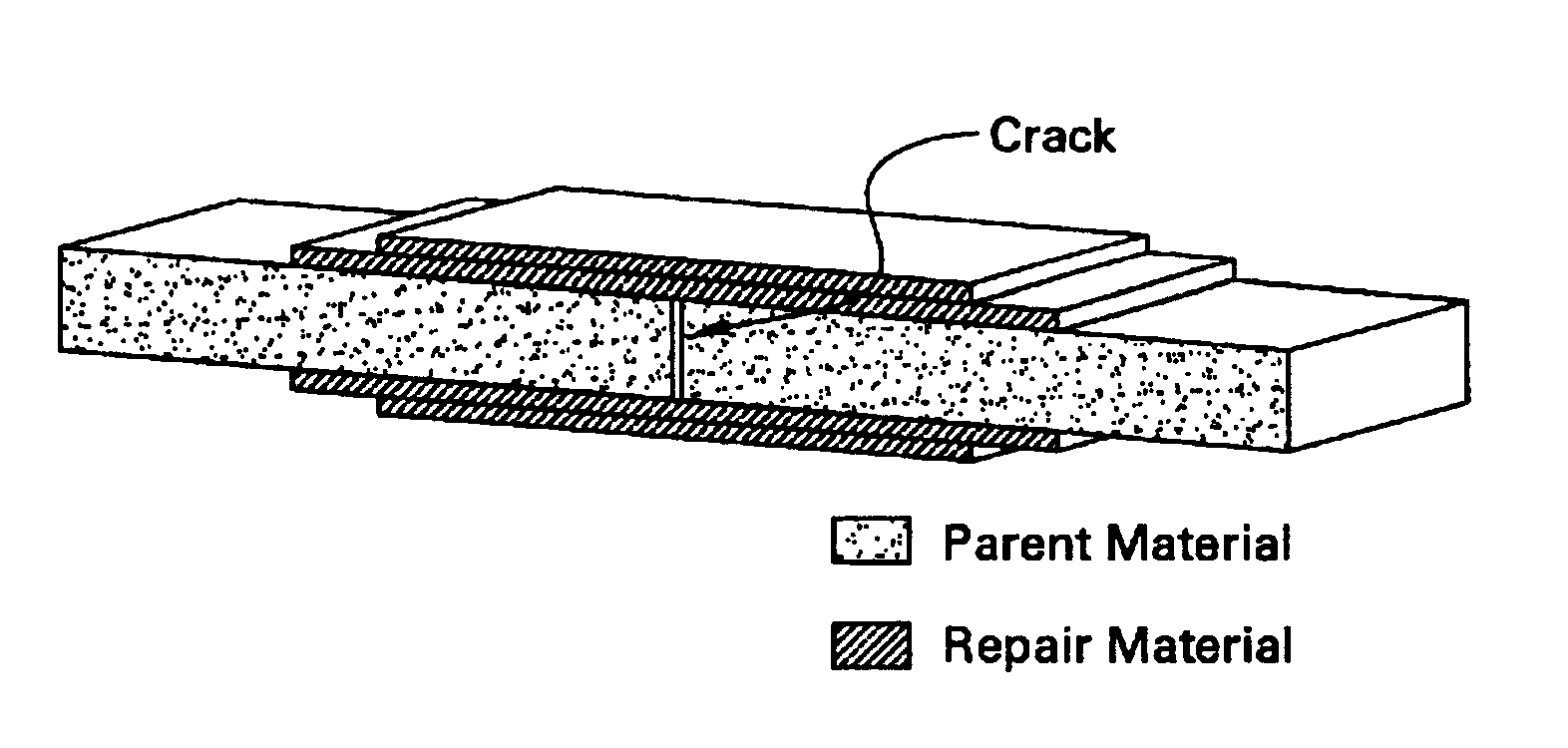
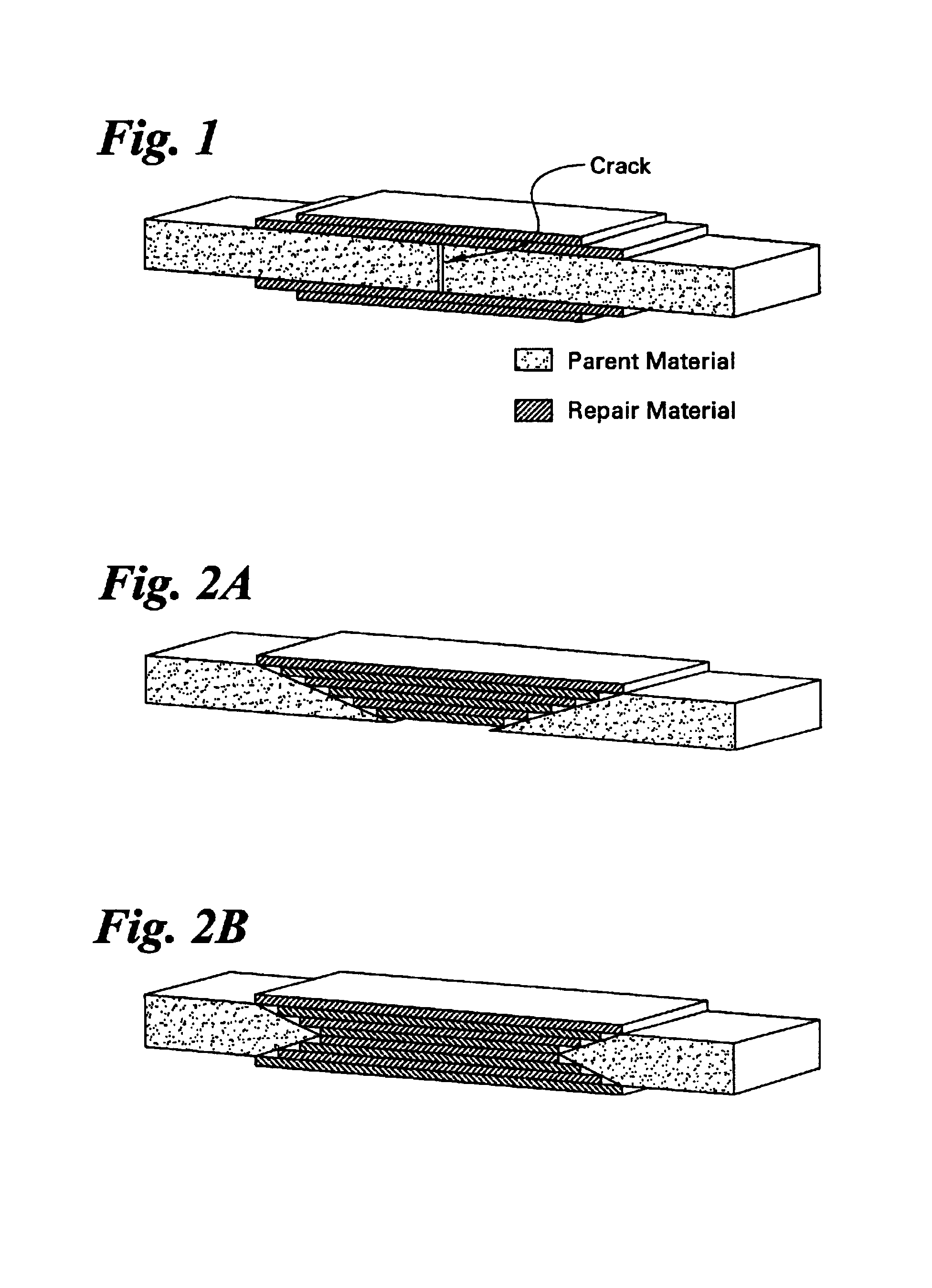
Two melt-infiltrated slurry cast Tyranno-ZMI.TM. SiC--SiC composite bars, each having a dimension of about 10 cm.times.1.25 cm.times.0.25 cm, were cut from a large plate. The surfaces of one of the bars were grit-blasted to remove residual layer of metal that was left behind during the fabrication of the plate. The metal residue on the as-fabricated surfaces of the second bar was removed by grinding. Both bars were cut into halves across the long dimension. The two halves of each bar were re-assembled. Two layers of sections of Hi-Nicalon.TM. prepreg tape were laid up on each of the grit-blasted surfaces of the bar and across the cut to cover an area about 2.5 cm on either side of the cut. The fibers in the prepreg tapes were applied to surfaces of the bar as exhibited in FIG. 1 and aligned to be per...

example 3

Repair by Applying a Plug Patch of Hi-Nicalon.TM. Fiber-Reinforced Prepreg Tape to a Melt-Infiltrated Fiber-Reinforced Prepreg Hi-Nicalon.TM. Composite Substrate

A tapered hole having a shape of an inverted prism, as shown in FIG. 2, was machined into a melt-infiltrated prepreg Hi-Nicalon.TM. SiC-in-SiC composite plate having a dimension of about 10 cm.times.2.5 cm.times.0.25 cm. The base of the hole had a large dimension of about 5 cm and a small dimension of about 0.8 cm. The hole was ground through the thickness of the plate. The wall of the hole was cleaned with acetone, and a thin layer of a paste prepared by mixing SiC and carbon powders with a phenolic resin and a binder was painted on the cleaned wall of the hole. The hole was then filled with layers of prepreg tape cut to appropriate dimensions. The patched CMC plate was subjected to a slow binder burnout up to about 750.degree. C. as described in Example 1. A pack consisting of silicon, boron, and boron nitride powders was ...

example 4

Repair by Applying a Plug Patch of Hi-Nicalon.TM. Fiber-Reinforced Prepreg Tape to a Melt-Infiltrated Slurry Cast Si--SiC Matrix Composite Reinforced with Tyranno-ZMI.TM. SiC Fibers

A tapered hole similar to that shown in FIG. 2 having a shape of an inverted prism was machined into a melt-infiltrated slurry cast Tyranno-ZMI.TM. SiC--SiC composite plate having a dimension of about 10 cm.times.3.8 cm.times.0.25 cm. The base of the hole had a large dimension of about 5 cm and a small dimension of about 0.8 cm. The hole was ground through the thickness of the plate. The wall of the hole was cleaned with acetone, and a thin layer of a paste prepared by mixing SiC and carbon powder with a phenolic resin and a binder was painted on the cleaned wall of the hole. The hole was then filled with layers of prepreg tape cut to appropriate dimensions. The patched CMC plate was subjected to a slow binder burnout up to about 750.degree. C. as described in Example 1. A pack consisting of silicon, boro...


PUM

PropertyMeasurementUnit
temperatureaaaaaaaaaa
diameteraaaaaaaaaa

Abstract

A method for repairing an article made of a fiber-reinforced ceramic matrix composite comprises attaching sections of a fiber-reinforced tape to the damaged area and then infiltrating the sections with the ceramic matrix or ceramic matrix precursor material. The material around the damaged area may be removed first to form a depression that is then filled with sections of the fiber-reinforced tape and further infiltrated with the ceramic matrix or ceramic matrix precursor material. The repaired article shows stress-strain curve similar to a defect-free article.

Description

BACKGROUND OF INVENTIONThe present invention relates to a method for repairing articles made of ceramic composites. In particular, the present invention relates to a method for repairing articles made of fiber-reinforced ceramic composites.Reinforced ceramic matrix composites ("CMCs") comprising fibers dispersed in continuous ceramic matrices of the same or a different composition are well suited for structural applications because of their toughness, thermal resistance, high-temperature strength, and chemical stability. Such composites typically have high strength-to-weight ratio that renders them attractive in applications in which weight is a concern, such as in aeronautic applications. Their stability at high temperatures renders them very suitable in applications in which the components are in contact with a high-temperature gas, such as in gas turbine engine.One process for the production of CMCs begins with producing a prepreg tape comprising fibers and a ceramic matrix or ma...

Claims


Application Information

Patent Timeline
Patent Type & Authority Patents(United States)
IPC IPC(8): B23P6/00B29C73/26B29C73/10B29C73/00F01D5/28B29C73/14C04B35/628C04B35/653C04B41/52C04B41/87
CPCB23P6/005B29C73/10B29C73/26C04B35/62868C04B35/62894C04B35/653C04B41/009C04B41/52C04B41/87F01D5/282C04B41/4539C04B41/5001C04B41/5059C04B41/53C04B41/4501C04B41/4554C04B41/4596C04B41/4545C04B41/5064C04B41/5094C04B41/5096C04B41/4523C04B35/565C04B35/806Y10T29/49318B29C73/14C04B2235/421C04B2235/428C04B2235/5244C04B2235/96Y02T50/672B23P2700/13Y10T29/49734Y10T29/49732C04B2235/614Y02T50/60
Inventor KEBBEDE, ANTENEHBRUN, MILIVOJ KONSTANTINLUTHRA, KRISHAN LALMCGUIGAN, HENRY CHARLES
Owner GENERAL ELECTRIC CO
Learn More