Disk drive mounting system for absorbing shock and vibration in a machining environment

a mounting system and machining environment technology, applied in the direction of instruments, casings/cabinets/drawers, electric apparatus casings/cabinets/drawers, etc., can solve the problems of more violent shaking of the machine, transmission of forceful jolt through the machine, and the machine can also be subjected to shock forces, so as to effectively isolate shock and vibration, effectively isolate vibration encountered in the machining environment, and isolate shock during shipment

Inactive Publication Date: 2004-11-23
SIEMENS IND INC
View PDF3 Cites 29 Cited by
  • Summary
  • Abstract
  • Description
  • Claims
  • Application Information

AI Technical Summary

Benefits of technology

It is another object of the present invention to provide a disk drive mounting system which effectively isolates shocks and vibrations;
Another object of the present invention is to provide a disk drive mounting system which effectively isolates vibrations encountered in a machining environment.
Yet another object of the present invention is to provide a disk drive mounting system which can isolate shock during shipment without requiring locking and unlocking of a device.
It is a further object of the present invention to provide a disk drive mounting system suitable for a machine tool environment which protects against disk drive damage, data loss, and / or data corruption.
A further object of the invention is to provide a disk drive mounting system which can be pre-assembled with a disk drive to create an assembly which is relatively simple to install at the site of use.
It is yet another object of the present invention to provide a disk drive mounting system which is cost effective and minimizes the number of parts needed.

Problems solved by technology

For example, a tool with few cutting teeth will typically cause more violent shaking of the machine than a tool with many cutting teeth.
In addition to vibration, such machines can also be subjected to shock forces during operation, as well as at other times. For example, during operation, if components collide at a substantial speed, a forceful jolt to the machine will occur which is transmitted through the machine.
As can be understood, significant vibrations and shocks which can arise in machine tool systems can interfere with the operation of machine components.
Disk drives in particular are susceptible to malfunctions due to vibration and shock, because of the tight spacing between the drive head and the memory medium and because of the precise placement of the information throughout the medium.
Accordingly, violent vibrations and shock can cause the drive head to contact the memory medium, thereby damaging the medium and / or the head.
Also, such vibrations and shock, if occurring during the drive operation, can cause data corruption and data loss.
While various damping and isolation systems have been proposed for protecting disk drives in machining environments, the problems of data loss and disk drive damage during operation still have not been completely solved.
Some mounting systems can actually amplify a transmitted vibration, causing damage to the components which were to be isolated.
Generally, damage results when the isolated component undergoes a deflection that exceeds the allowable sway space, causing the component to contact a hard surface.
Moreover, while various wedges, clamps, solenoids, and other lock-down devices have been utilized for protecting drives during shipment, such devices are not without disadvantages.
For example, the lock-down device can inadvertently become unlocked or be inadequate for the shock that is experienced.
Moreover, if one forgets to lock the device before shipment or to unlock the device after shipment, data loss and drive damage can occur.
However, such pads typically only limit movement in a single linear direction.

Method used


Image

  • Disk drive mounting system for absorbing shock and vibration in a machining environment
  • Disk drive mounting system for absorbing shock and vibration in a machining environment
  • Disk drive mounting system for absorbing shock and vibration in a machining environment

Examples


Embodiment Construction

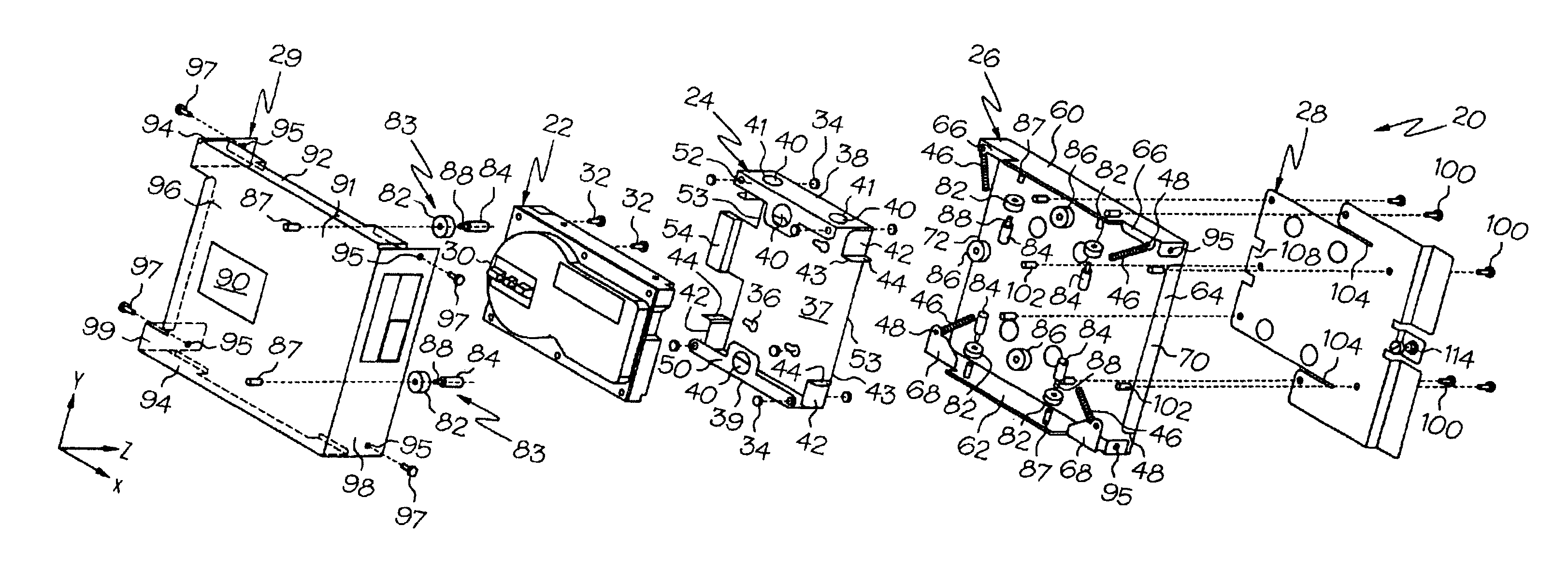
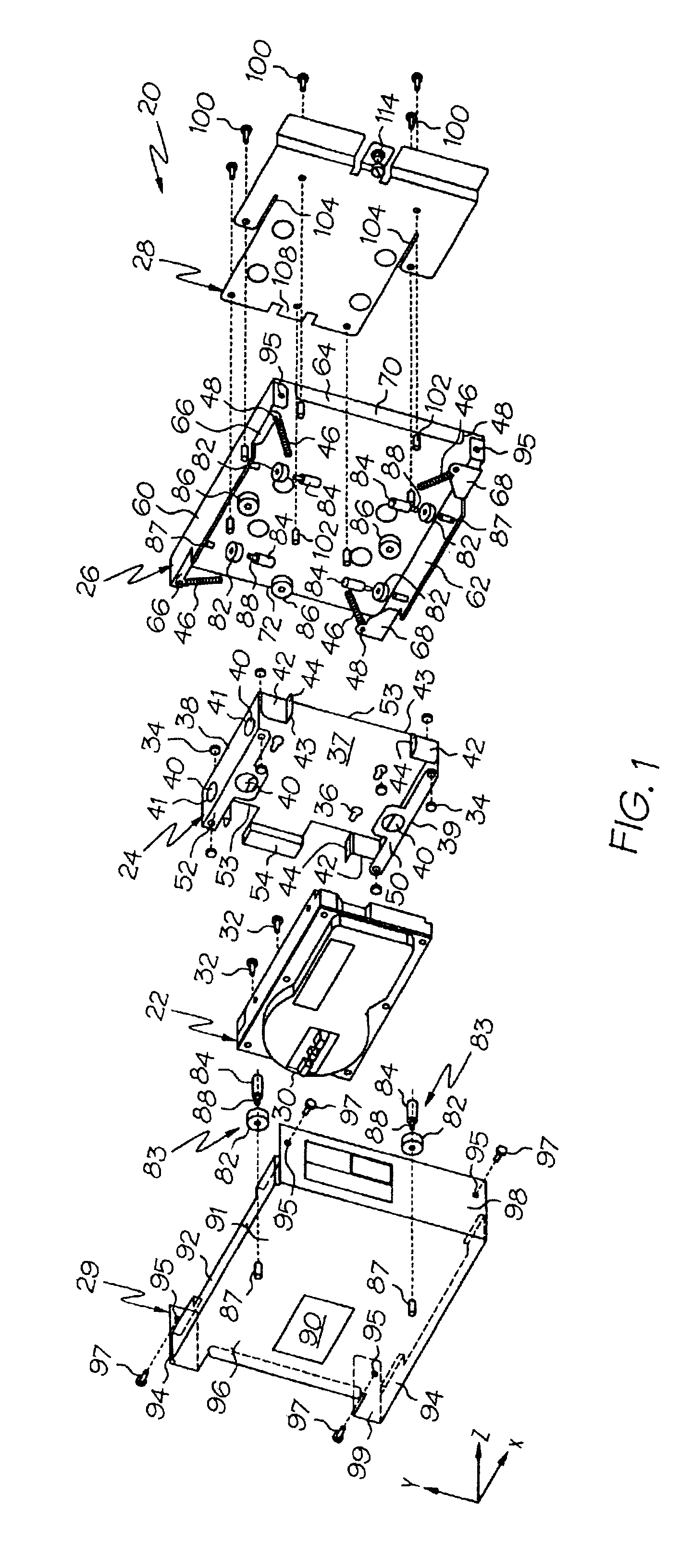
Turning now to the drawings in detail, wherein like numbers illustrate corresponding structure, FIG. 1 is an exploded perspective view of one embodiment of a disk drive mounting system 20, made in accordance with principles of the present invention. In this embodiment, the assembly 20 comprises a disk drive assembly 22, a disk drive mounting chassis 24, a suspension frame 26, a bracket 28, and a cover 29.

The disk drive assembly 22 preferably comprises a read / write head, a housing, and a memory disk having data for use in operating a machine tool system. For example, the disk drive 22 could comprise a Model QM31620ST-A hard disk drive made by Quantum Corp. In addition to hard disk drives, the disk drive 22 could comprise any of a variety of drives used to store data, such as CD ROM drives, floppy disk drives, and ZIP drives for example. The disk drive 22 can include indicators 30, such as to display the operation mode of the drive, and / or to indicate that a shock has been experienced...


PUM

PropertyMeasurementUnit
angleaaaaaaaaaa
vibration frequenciesaaaaaaaaaa
natural frequencyaaaaaaaaaa

Abstract

A disk drive mounting system for isolating a disk drive assembly from machine vibration and shock. In one embodiment, the system includes a suspension frame and a disk drive assembly mounted to the frame using biased vibration isolation members, such as springs, which are each substantially aligned through the center of mass of the disk drive assembly. Accordingly, vibrational forces can be transmitted through the center of mass of the disk drive assembly. Preferably, the disk drive assembly includes a mounting chassis which holds a hard disk drive and includes openings through which damping bumpers can extend. In this embodiment, the bumpers each have a base portion and an extension portion, the extension portion extending through the openings in the mounting chassis to limit the transfer of shock to the disk drive. The bumpers can be attached to the suspension frame and / or to a protective cover for the assembly. Preferably, a slide bracket is provided to allow the system to be easily mounted to a machine tool system surface.

Description

TECHNICAL FIELDThe present invention relates generally to a disk drive mounting system for machine tools and other applications having vibrations in a particular range of frequencies. In particular, the invention relates to a hard drive mounting system having a suspension configuration in which the vibration isolation members are provided near the corners of a hard drive mounting chassis and substantially aligned through the center of gravity of the hard drive / mounting chassis structure. The present invention also relates to a hard drive transportation system which includes damping members which protrude through holes in the hard drive mounting chassis.BACKGROUND OF THE INVENTIONThe use of disk drives in machining applications has become commonplace. In such uses, the disk drive stores data and instructions for controlling the operation of a machine tool. Such machines are typically driven by one or more electric motors which rotate either the tool or the part to be machined during ...

Claims


Application Information

Patent Timeline
Patent Type & Authority Patents(United States)
IPC IPC(8): G11B33/08
CPCG11B33/08
Inventor ALLGEYER, THOMAS L.KEMP, JAMES J.LEIGHTY, CLIFFORD A.NOE, JEFF J.
Owner SIEMENS IND INC
Why Eureka
Try Eureka