Methods and devices for inhibiting battery voltage delays in an implantable cardiac device

a battery and implantable technology, applied in the field of implantable cardiac devices, can solve the problems of affecting the patient's vital therapy, affecting the patient's recovery, and reducing the efficiency of the treatment process,

Inactive Publication Date: 2004-11-30
PACESETTER INC
View PDF5 Cites 22 Cited by
  • Summary
  • Abstract
  • Description
  • Claims
  • Application Information

AI Technical Summary

Problems solved by technology

This is undesirable because a battery with an excessively high ESR will ultimately be unable to deliver sufficient current to the circuitry of the ICD leading to a potentially catastrophic result to the patient.
Batteries with an ESR that is higher than normal also take longer to charge the capacitor of the ICD, thus potentially delaying the delivery of vital therapy to the patient.
While this technique is effective in reducing battery ESR, it should not be used more often than about once a month because the process is extremely energy-inefficient.
If this is performed on a regular schedule to limit ESR development in the battery, it would squander a large amount of battery energy.
However, the charging performance during the first cycle was well below expected performance characteristics for an ICD.
In a clinical setting, such a delay in application of a countershock from the ICD's capacitors could have potentially disastrous consequences for the patient in whom the device is implanted.
However, as the design and fabrication of capacitors continues to improve, the requirement for periodic capacitor "reforming" may eventually become unnecessary, and there may be no other need for this regular and highly inefficient use of stored battery energy.
As shown in FIG. 5, the voltage delay can lead to a significant voltage decrease during the start of charging.
A problem with this approach is that approximately 50 joules of energy per month are wasted, thereby significantly reducing the life span of battery 110.
However, this method is not optimal because most deformation of capacitor 330 typically occurs in about the first 7 days after reforming, and then quickly reaches equilibrium.

Method used


Image

  • Methods and devices for inhibiting battery voltage delays in an implantable cardiac device
  • Methods and devices for inhibiting battery voltage delays in an implantable cardiac device
  • Methods and devices for inhibiting battery voltage delays in an implantable cardiac device

Examples


Embodiment Construction

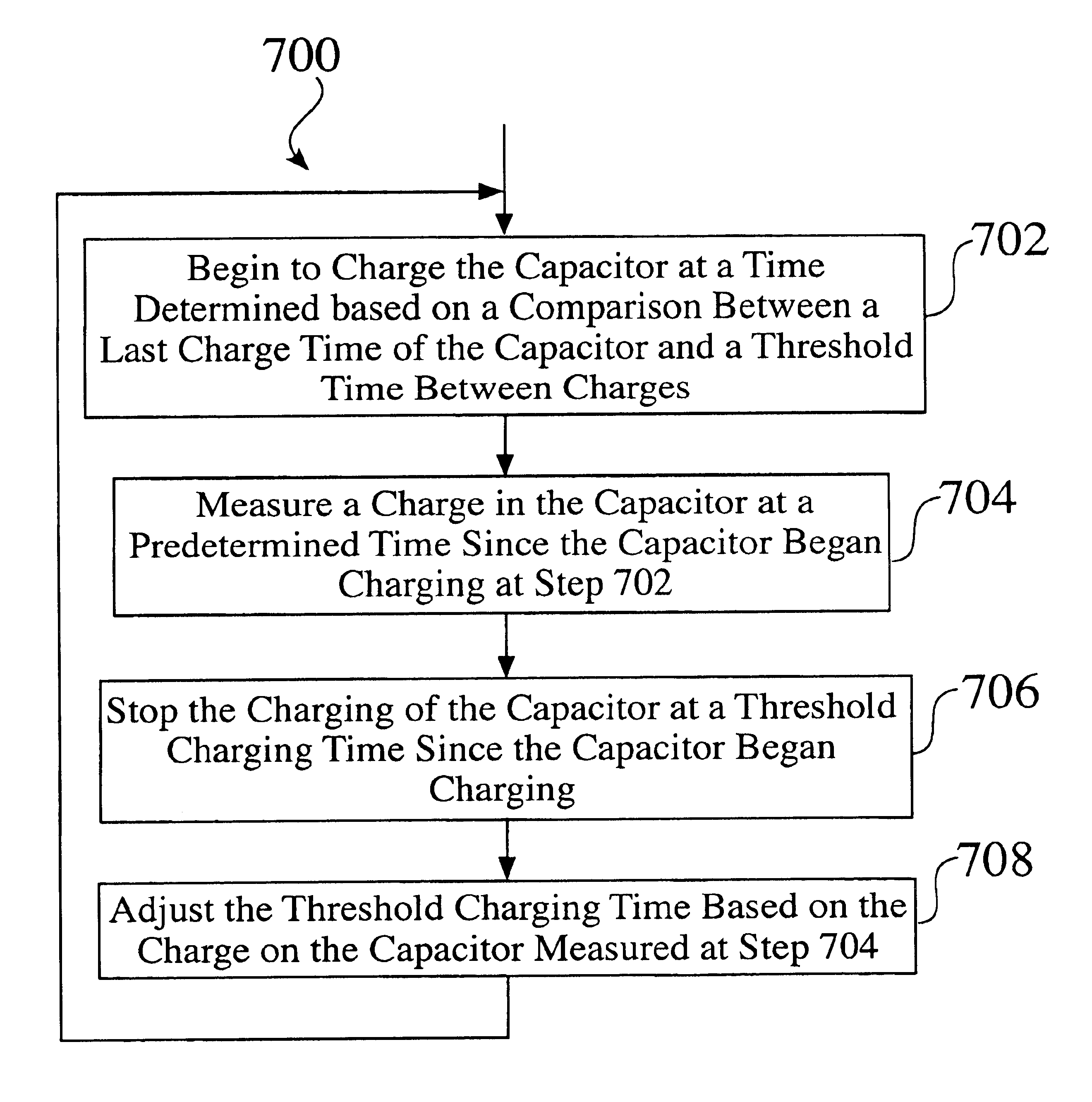
FIG. 7 illustrates a flow diagram of a method 700 useful for describing an overview of the operation of embodiments of the present invention. At a first step 702, capacitor 330 begins to be charged at a time determined based on a comparison between a time since a last charge of the capacitor and a threshold time between charges. For example, the charging of the capacitor begins when the time since the last charge of the capacitor equals the threshold time between charges. An exemplary threshold time between charges is about 10 days. If this were the case, capacitor 330 would be charged about three times per month. Preferably, the threshold time between charges is set to be between about 5 days and about 10 days. The less frequent the time between charges and the less energy drawn from battery 110 each time capacitor 330 is charged, the longer the life of battery 110 will last.

At a next step 704, a charge on capacitor 330 is measured at a predetermined time (e.g., 0.5 seconds) since ...


PUM


Abstract

A battery of a cardiac stimulation device may experience voltage delay problems caused by a passivation layer that forms on the anode of the battery. To inhibit voltage delay, the battery is periodically used to charge the capacitor to a partial charge. Both the charge time and the interval between charges can be adjusted to reduce the power consumption required to inhibit battery voltage delay.

Description

1. Field of the InventionThe present invention relates generally to implantable cardiac devices, such as implantable cardioverter defibrillators (ICDs). The present invention more particularly relates to inhibiting voltage delay in a battery of an implantable cardiac device.2. Background ArtImplantable cardiac devices, such as implantable cardioverter defibrillators (ICDs), are well known in the art. Such devices are generally implanted in a pectoral region of the chest beneath the skin of a patient within what is known as a subcutaneous pocket. The primary components of an ID include a monitoring and detection mechanism, a capacitor, a battery, a sensing system for detecting an arrhythmia, and a control system for controlling delivery of a capacitive discharge electrical shock in response to a detected arrhythmia by charging and then discharging the capacitor. The implantable devices generally function in association with one or more electrode carrying leads which are implanted wit...

Claims


Application Information

Patent Timeline
Patent Type & Authority Patents(United States)
IPC IPC(8): A61N1/39
CPCA61N1/3975A61N1/3962A61N1/39622
Inventor FAYRAM, TIMOTHY A.KROLL, MARK W.
Owner PACESETTER INC
Why Eureka
Try Eureka