Secondary air supply abnormality detection system

an abnormality detection and air supply technology, applied in mechanical equipment, machines/engines, electric control, etc., can solve the problems of increasing catalyst temperature, large calculation error generation, and increasing cost unavoidabl

Inactive Publication Date: 2004-12-14
DENSO CORP
View PDF4 Cites 26 Cited by
  • Summary
  • Abstract
  • Description
  • Claims
  • Application Information

AI Technical Summary

Benefits of technology

It is another object of the present invention to provide a secondary air supply abnormality detection system for an internal combustion engine enabling a vehicle to travel to a safe place when an abnormality in a flow rate of secondary air supplied from a secondary air supply system is detected, while preventing thermal degradation of a catalyst.
According to an aspect of the present invention, a secondary air supply abnormality detection system for an internal combustion engine includes air-fuel ratio estimating means, air-fuel ratio sensing means, secondary air flow rate calculating means and abnormality determining means. The air-fuel ratio estimating means estimates an air-fuel ratio of air-fuel mixture supplied to the engine. The air-fuel ratio sensing means senses an air-fuel ratio. The secondary air flow rate calculating means calculates a flow rate of the secondary air supplied from the secondary air supply system based on the air-fuel ratio of the air-fuel mixture supplied to the engine, which is estimated by the air-fuel ratio estimating means, and the air-fuel ratio, which is sensed by the air-fuel ratio sensing means when the secondary air is supplied from the secondary air supply system. The abnormality determining means determines an abnormality in a system including the secondary air supply system based on the calculated secondary air flow rate. Thus, the secondary air flow rate can be calculated highly accurately independently of the air-fuel ratio of a flow downstream of the secondary air. As a result, the abnormality in the system including the secondary air supply system can be detected accurately.
According to another aspect of the present invention, the secondary air supply abnormality detection system for the internal combustion engine includes abnormality determining means. The abnormality determining means determines that an abnormality is generated in the system including the secondary air supply system if an air-fuel ratio deviation between the air-fuel ratio of the air-fuel mixture supplied to the engine and the air-fuel ratio, which is sensed by the air-fuel ratio sensing means when the secondary air is supplied from the secondary air supply system, is not in a predetermined range. Thus, the air-fuel ratio deviation can be calculated highly accurately independently of the air-fuel ratio of the flow downstream of the secondary air, and the abnormality in the system including the secondary air supply system can be detected highly accurately.
According to yet another aspect of the present invention, abnormality determining means determines the abnormality in the flow rate of the secondary air supplied from the secondary air supply system. If it is determined that the secondary air supply system is in the abnormal state, air intake quantity supplied to the internal combustion engine is restricted. Thus, temperature increase of a catalyst beyond limit temperature, above which thermal degradation of the catalyst is caused, can be prevented when the secondary air supply system is in the abnormal state. The excessive temperature increase of the catalyst is cause when intake air quantity is excessive.

Problems solved by technology

However, in this method, an increase in the cost is unavoidable because of the additional sensors and the like.
In addition, there is a possibility that a large calculation error is generated because the secondary air flow rate is calculated in one time.
If the secondary air supply system is brought to an abnormal state and keeps supplying the secondary air, the temperature of the catalyst increases rapidly and the catalyst main body will be heated excessively.
If it is determined that the secondary air supply system is in the abnormal state, air intake quantity supplied to the internal combustion engine is restricted.
The excessive temperature increase of the catalyst is cause when intake air quantity is excessive.

Method used


Image

  • Secondary air supply abnormality detection system
  • Secondary air supply abnormality detection system
  • Secondary air supply abnormality detection system

Examples


first embodiment

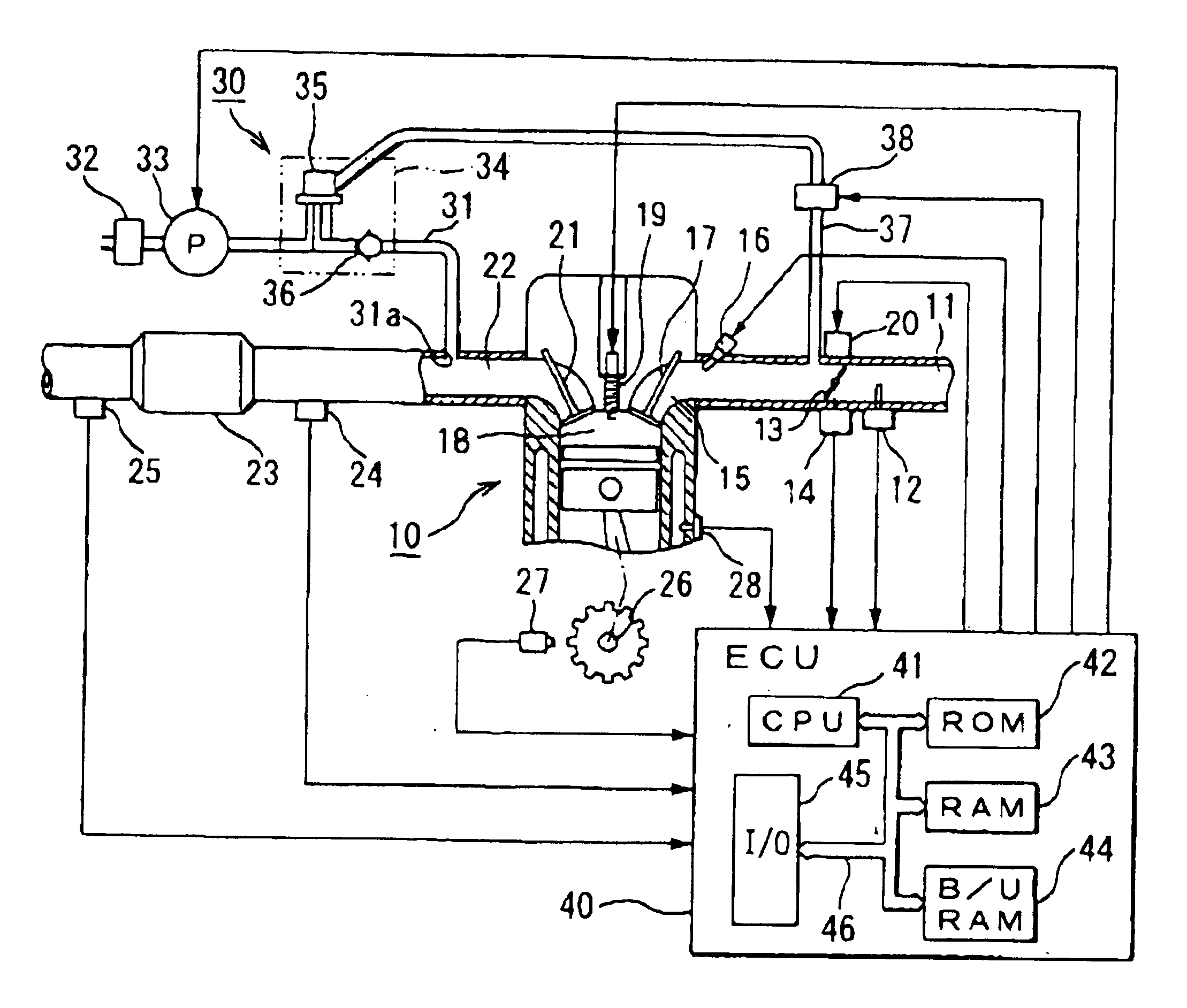
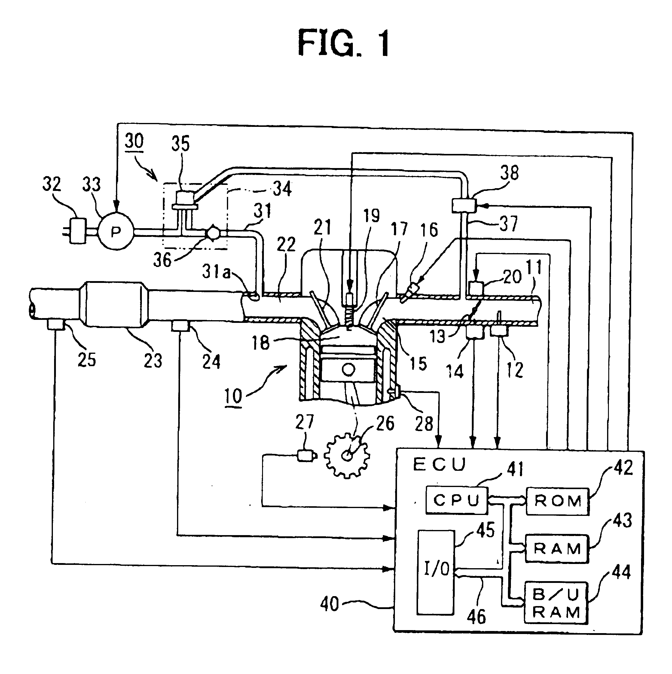
Referring to FIG. 1, an internal combustion engine 10 having a secondary air supply abnormality detection system according to the first embodiment of the present invention is illustrated. As shown in FIG. 1, an airflow meter 12 for sensing a quantity of intake air supplied through an air cleaner is disposed on an upstream side of an air intake passage 11 of the engine 10. A throttle valve 13 for regulating the air intake quantity to the engine 10 is disposed downstream of the airflow meter 12. A direct current motor 20 as an actuator constituting an electronic throttle structure drives the throttle valve 13 to open or close. A throttle opening degree sensor 14 for sensing an opening degree of the throttle valve 13 is disposed on the throttle valve 13. In the air intake passage 11, an injector (a fuel injection valve) 16 is disposed near an intake port 15 of each cylinder of the engine 10.

Mixture of intake air of a quantity defined by the throttle valve 13 and fuel supplied by the in...

second embodiment

Next, processing steps of secondary air supply abnormality detection performed by the CPU 41 of the ECU 40 used in the secondary air supply abnormality detection system of the internal combustion engine 10 according to the second embodiment of the present invention will be explained based on a flowchart shown in FIG. 4 and the time chart shown in FIG. 3. The secondary air supply abnormality detection routine shown by the flowchart in FIG. 4 is performed by the CPU 41 repeatedly at a predetermined time interval. The secondary air supply abnormality detection system of the second embodiment has the same structure as the first embodiment.

First, in Step S201 of the flowchart in FIG. 4, like the first embodiment, it is determined whether conditions for the diagnosis are established or not. The conditions for the diagnosis include a condition that the air-fuel ratio sensor 24 is active, a condition that the operating state is steady (without rapid change), a condition that a predetermined...

third embodiment

Next, processing steps of secondary air supply abnormality determination performed by the CPU 41 of the ECU 40 used in the secondary air supply abnormality detection system for the internal combustion engine 10 according to the third embodiment will be explained based on a flowchart shown in FIG. 5. The CPU 41 performs the secondary air supply abnormality determination routine at a predetermined time interval.

First, in Step S301 shown in FIG. 5, it is determined whether duration t.sub.air after the air pump 33 is switched from an operating state (ON) to a dormant state (OFF) is longer than a predetermined period t.beta.. The predetermined period t.beta. is a period for stabilizing the secondary air downstream air-fuel ratio .lambda.AFS after the supply of the secondary air is stopped. If the result of the determination in Step S301 is "NO", the routine is ended without performing anything.

On the other hand, if the result of the determination in Step S301 is "YES", the processing pro...


PUM


Abstract

A secondary air supply abnormality detection system determines that an abnormality is generated in a system including a secondary air supply system if a true secondary air flow rate is out of a predetermined range. The true secondary air flow rate is calculated by subtracting a secondary air flow rate average at the time when an air pump is not operating from another secondary air flow rate average at the time when the air pump is operating. Thus, variation in the secondary air flow rate due to change with time or production tolerance can be suitably corrected. Since calculation accuracy of the true secondary air flow rate is improved, determination accuracy of the abnormality in the system including the secondary air supply system can be improved.

Description

This application is based on and incorporates herein by reference Japanese Patent Applications No. 2002-372140 filed on Dec. 24, 2002 and No. 2003-78725 filed on Mar. 20, 2003.1. Field of the InventionThe present invention relates to a secondary air supply abnormality detection system of an internal combustion engine for detecting an abnormality in secondary air supply, which is performed in order to activate a catalyst disposed in an exhaust passage of the internal combustion engine.2. Description of Related ArtConventionally, a method of sensing a flow rate of secondary air directly by using a pressure sensor or a flow rate sensor in order to detect an abnormality in secondary air supply in an internal combustion engine is known. However, in this method, an increase in the cost is unavoidable because of the additional sensors and the like.A technology relating to the above method is disclosed in Japanese Patent Unexamined Publication No. H06-146867 (pages 2 and 3). In this technol...

Claims


Application Information

Patent Timeline
Patent Type & Authority Patents(United States)
IPC IPC(8): F01N11/00
CPCF01N11/00Y02T10/47F01N2550/14Y02T10/40
Inventor MORINAGA, SHUJIROUSAGO, KENICHIKODOU, SATOSHIFUJIKI, KENICHIKITA, MASAYUKI
Owner DENSO CORP
Why Eureka
Try Eureka