Cycle wheel safety lighting system

a safety lighting and bicycle technology, applied in the direction of lighting and heating equipment, bicycle equipment, optical signals, etc., can solve the problems of serious injury or worse, bicyclists are often caught off guard, and cannot always time their ride tim

Inactive Publication Date: 2004-12-21
FROSYTHE GARY +1
View PDF8 Cites 21 Cited by
  • Summary
  • Abstract
  • Description
  • Claims
  • Application Information

AI Technical Summary

Benefits of technology

It is another object of this invention to provide a bicycle safety light system that will be simple to use and maintain, thereby assuring a high level of use.
In one aspect, this invention features a cycle wheel safety lighting system having a plurality of electro-luminescent panels spaced about the wheels of a bicycle for rotation therewith, electrical power means to energize the light emitting panels causing the panels to light up, and power control means for controlling delivery of electrical power to the panels to provide a bright, pulsating visual image when the cycle is in motion.

Problems solved by technology

Also, many adults ride bicycles for transportation and cannot always time their ride time to occur only bright daylight hours.
In addition, bicyclists are frequently caught away from home base at the onset of rain showers, when light is diminished due to lack of sun and the incidence of rain, and are forced to travel at those times.
In all these instances, the diminished lighting poses serious risk of inadequate visibility of the cyclist to motorists driving cars and trucks, and the all-too-real possibility of being struck, resulting in serious injury or worse.
None of these adequately positively identifies a bicyclist to motorists at a sufficiently safe distance.
There has been no known commercialization of any of these devices.
Children are notorious for forgetting to wear or use safety devices, usually thinking of them as nuisances.

Method used


Image

  • Cycle wheel safety lighting system
  • Cycle wheel safety lighting system
  • Cycle wheel safety lighting system

Examples


Embodiment Construction

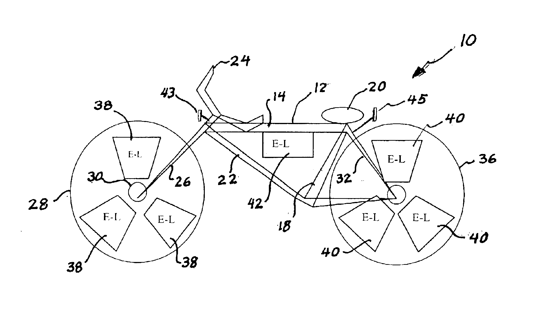
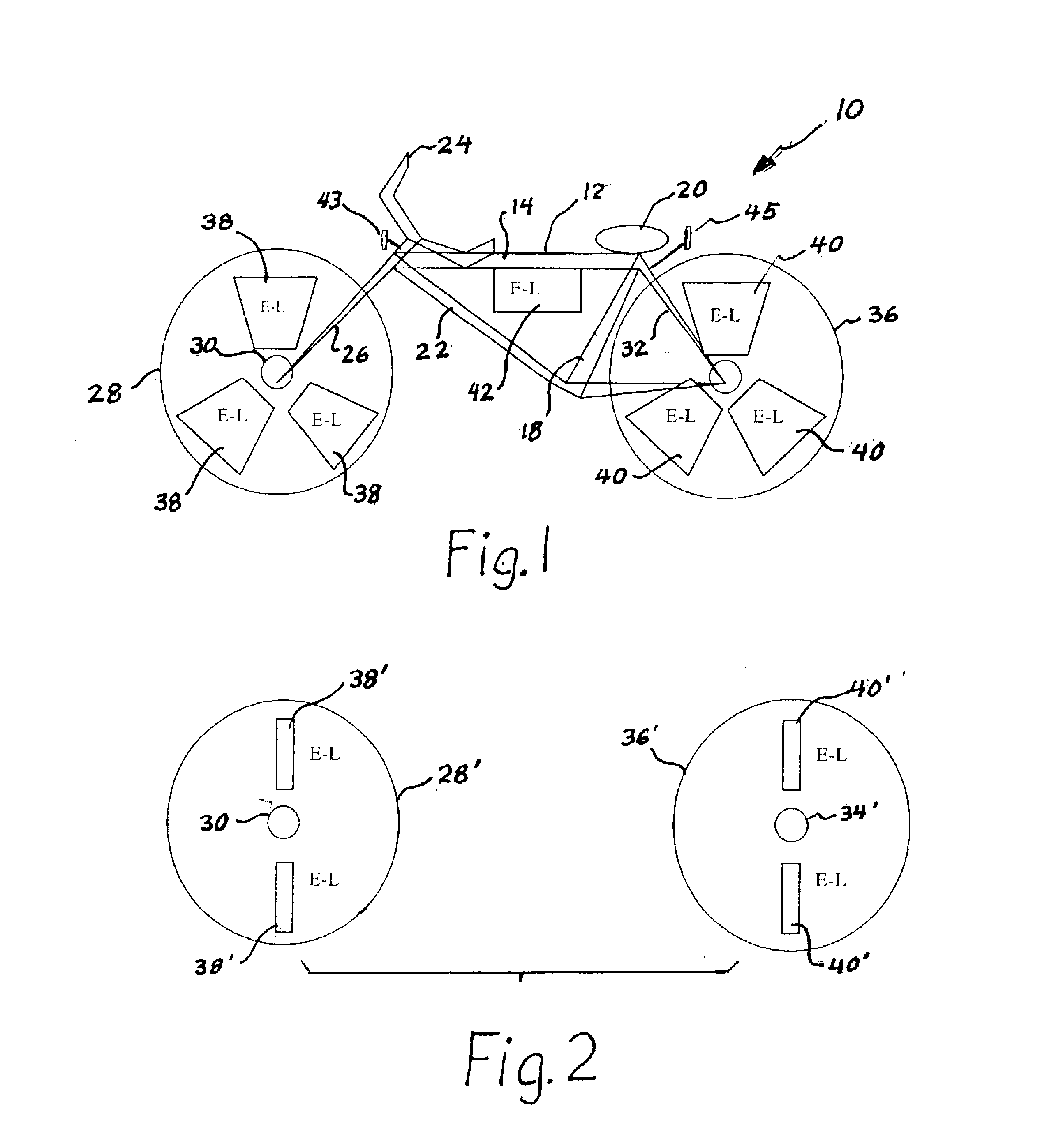
FIG. 1 shows a schematic side view of a bicycle 10 having a lighting system according to this invention. Bicycle 10 includes the usual frame 12, having a horizontal bars 1 that interconnects a steering post 16 and a rear post 18, that mounts a seat 20 for the rider, not illustrated. An angled main frame bar 22 completes frame 12. Steering post 16 mounts handlebars 24 and interconnected front fork 26 that mounts a spoked front wheel 28 (spokes not illustrated) having a hub 30. A forked rear brace 30 and rear post 18 mount the ends of a rear fork 32 that mounts a hub 34 of a spoked rear wheel 36. The conventional chain-and-sprocket drive mechanism is not shown.

Three identical trapezoidal electro-luminescent (E-L) light panels 38 are spaced about and secured to front wheel 26, while similar panels 40 are spaced about and secured to rear wheel 36. Another electro-luminescent light panel 42 is mounted on frame bar 14, while a front facing panel 43 and a rear facing panel 45 are mounted o...


PUM


Abstract

A Cycle Wheel Safety Light System uses double-sided shaped A-C electro-luminescent light panels, spaced about the wheels of a bicycle. A DC battery powers the panels via a DC-AC inverter. Alternatively, an alternator mounted between the wheel axle and frame utilizes the bicycle rider's motive power as the source of energy. Another variation combining the best features of both the battery and inverter is use of an alternator to charge (via a rectifier) a smaller battery or other energy storage device such as a 'supercap'. The panels may be of various colors to improve the "WOW!" factor and encourage adolescent use.

Description

1. Technical FieldThe present invention relates to a system for identifying a bicycle during operation during periods of low light, such as dawn, dusk and night hours, where visibility to approaching vehicular traffic is diminished and illumination of objects is impaired.2. Description of the Prior ArtRiders of bicycles, mopeds and similar vehicles frequently ride in the streets during periods of diminished light, especially at dusk. This often occurs for child cyclists during summertime when they are away from home playing or involved in organized activities, such as sports. Also, many adults ride bicycles for transportation and cannot always time their ride time to occur only bright daylight hours. In addition, bicyclists are frequently caught away from home base at the onset of rain showers, when light is diminished due to lack of sun and the incidence of rain, and are forced to travel at those times.In all these instances, the diminished lighting poses serious risk of inadequate...

Claims


Application Information

Patent Timeline
Patent Type & Authority Patents(United States)
IPC IPC(8): B62J6/00B62J6/20
CPCB62J6/20Y10S362/802
Inventor FROSYTHE, GARYSTOUTENBURG, DONN V.
Owner FROSYTHE GARY
Why Eureka
Try Eureka