Beam steering apparatus for a traveling wave antenna and associated method

a technology of traveling wave antenna and steering apparatus, which is applied in the direction of electrical apparatus, leaky waveguide antenna, antenna, etc., can solve the problems of complex mechanical construction, large antenna, and inability to achieve beam steering in a simple manner, and achieve the effect of simple construction

Inactive Publication Date: 2004-12-21
HRL LAB
View PDF14 Cites 15 Cited by
  • Summary
  • Abstract
  • Description
  • Claims
  • Application Information

AI Technical Summary

Benefits of technology

A further object of the invention is to provide such apparatus which is simple in construction and can be adapted to a conventional waveguide of a traveling wave antenna.

Problems solved by technology

The waveguides in these patents lack the ability to achieve beam steering in a simple manner.
Such antennas are often very large and involve complex mechanical constructions to rotate the plate.
Furthermore, they are relatively costly and add significantly to the overall antenna height.

Method used


Image

  • Beam steering apparatus for a traveling wave antenna and associated method
  • Beam steering apparatus for a traveling wave antenna and associated method
  • Beam steering apparatus for a traveling wave antenna and associated method

Examples


Embodiment Construction

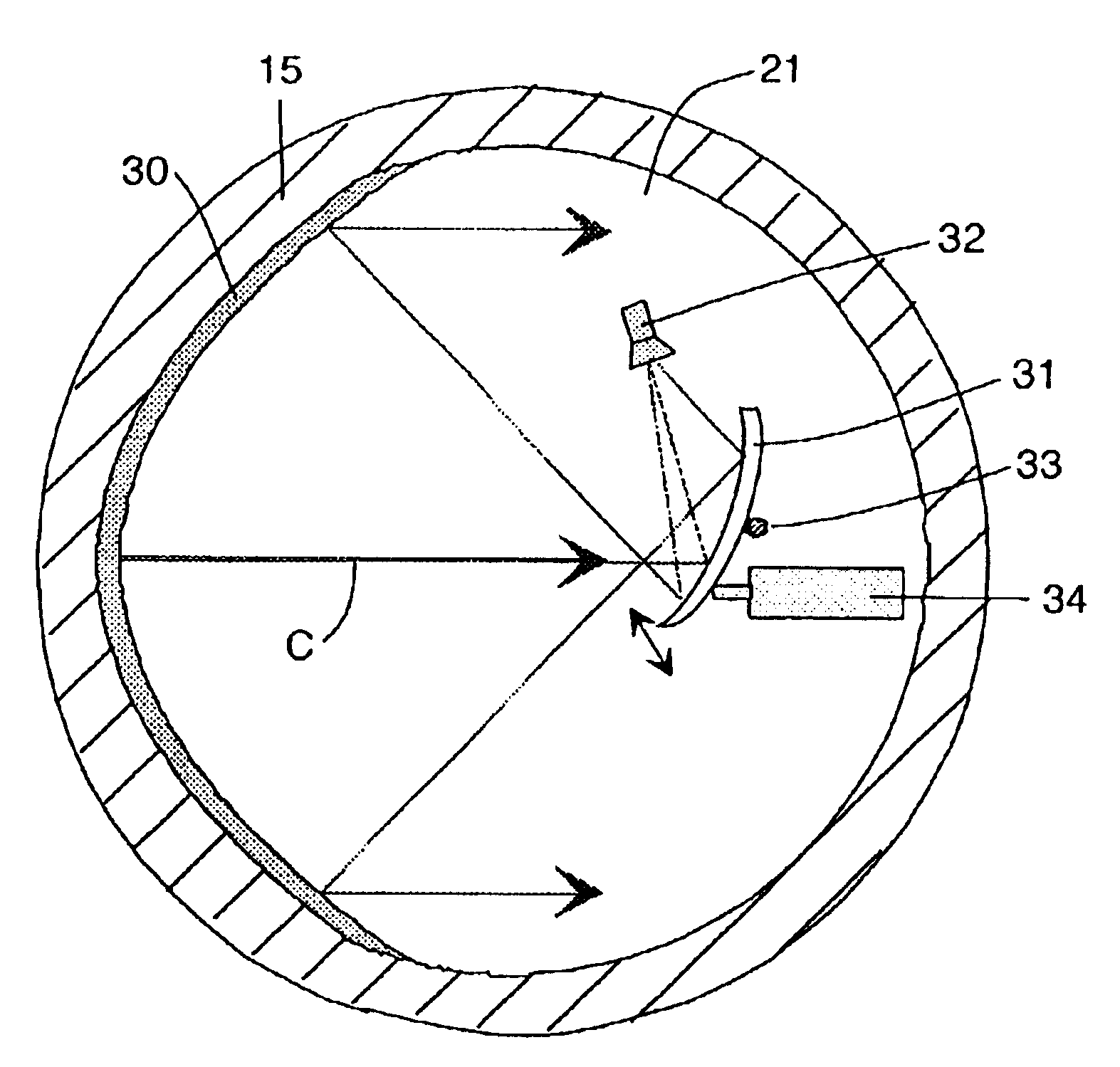
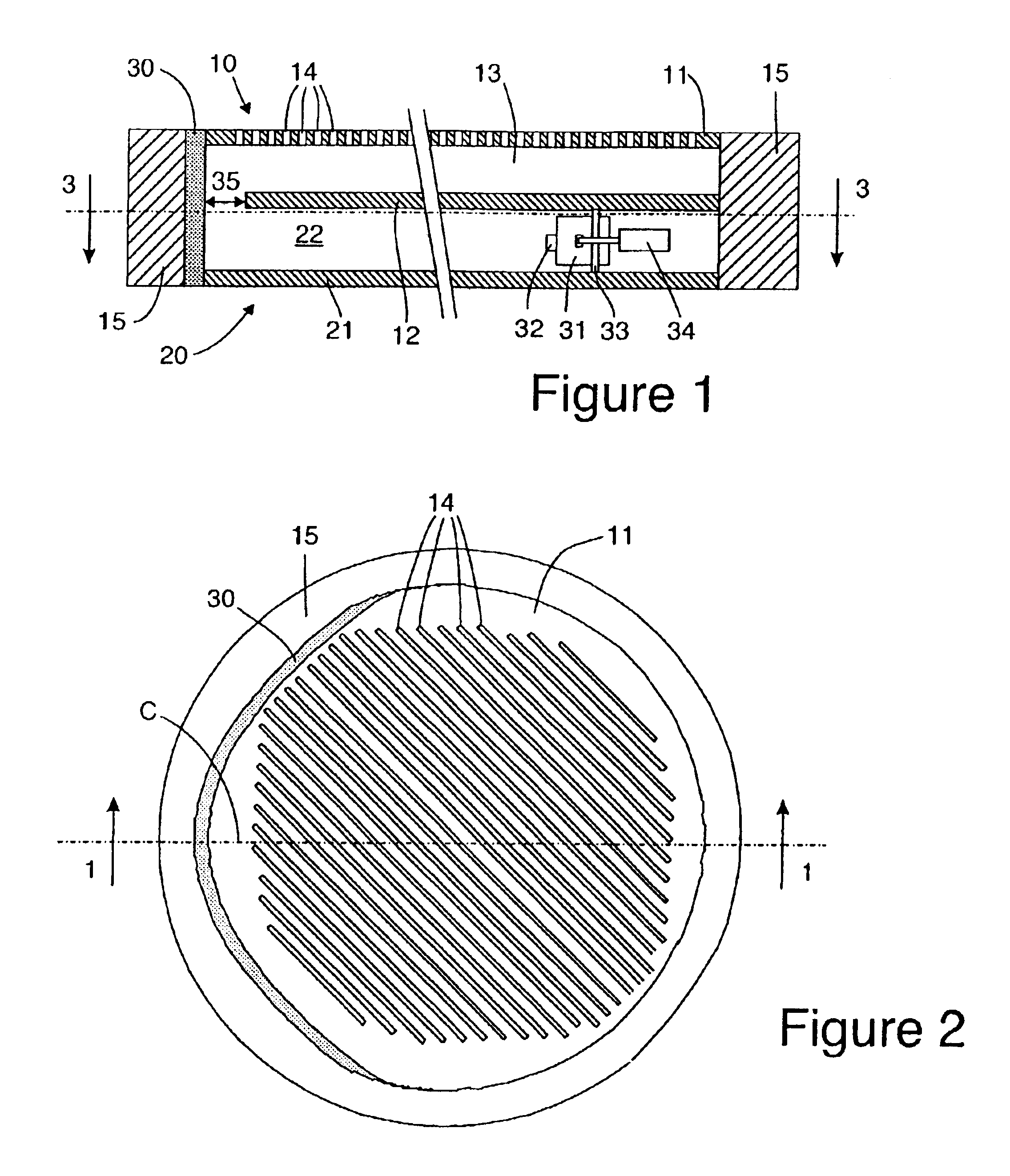
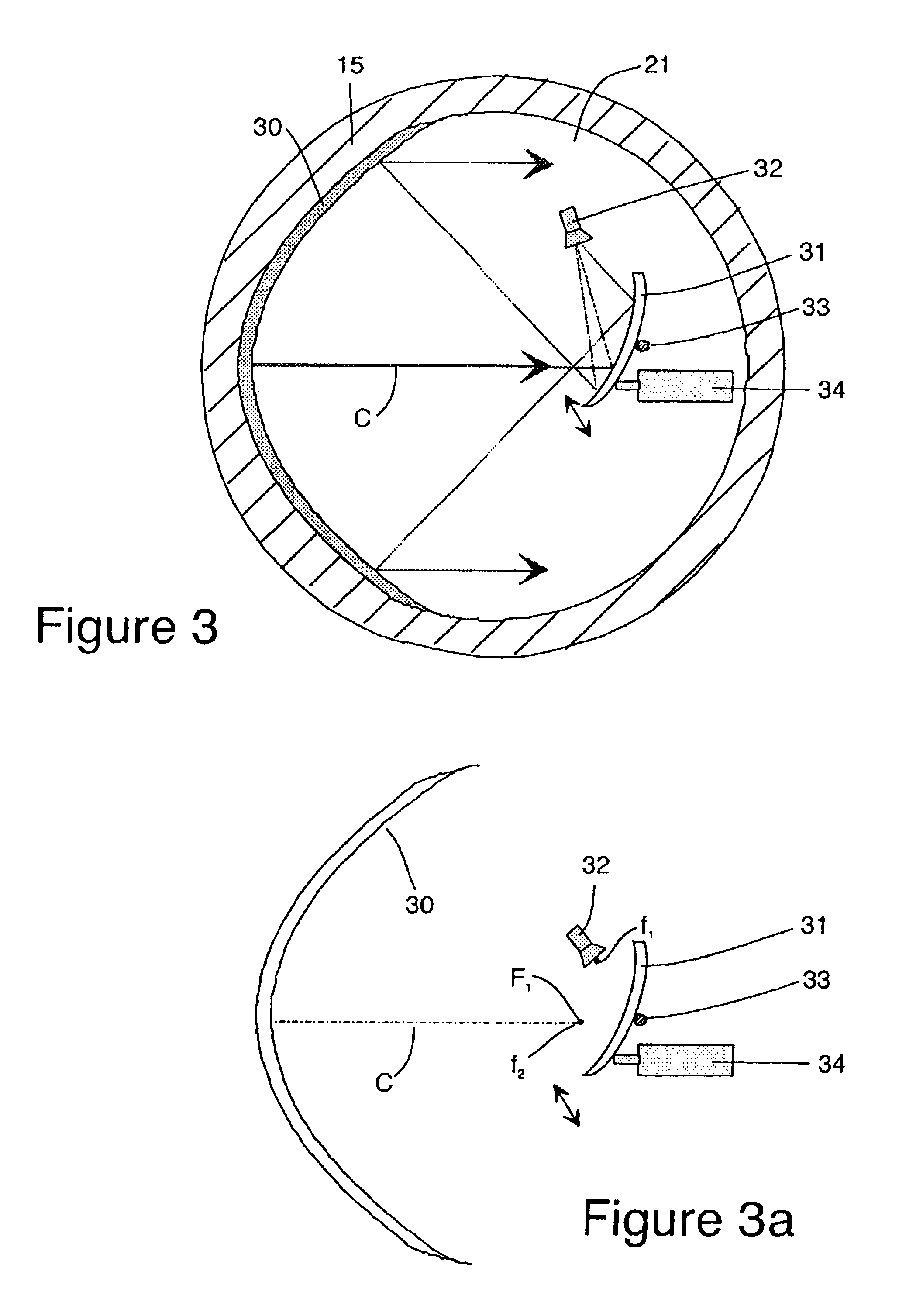
Referring to FIG. 1 of the drawing, therein can be seen a portion of an embodiment of a waveguide 10 for a traveling wave antenna. The waveguide 10 comprises an upper conductive plate 11 and a parallel lower conductive plate 12, separated by a dielectric medium 13. Plates 11 and 12 are preferably attached to a conductive outer wall 15. The upper plate 11 is provided with radiating apertures 14 dimensioned to provide the proper amplitude and phase distribution of the radiated energy along the length of the waveguide 10 of the antenna to its outlet end. The apertures 14 generally extend substantially across the entire width of the upper plate 11 as shown in FIG. 2. The apertures 14 are shown as rectangular slots, although other shapes are well known to those skilled in the art. The dielectric medium 13 is preferably a foam material.

Up to this point in this description, the waveguide 10 is substantially conventional and normally an energy source produces the beam or wave which travels ...


PUM


Abstract

Steering of an electromagnetic beam of energy in the upper plate of a plate waveguide of a traveling wave antenna concurrently with the formation of a flat phase front and collimation of the electromagnetic beam is achieved by providing a second waveguide beneath the lower plate of the first waveguide and providing a 180% bend parabolic main reflector to reflect the energy beam to the upper plate of the upper waveguide. A feed horn is located in the lower waveguide and illuminates a pivotal subreflector which reflects the energy to the parabolic main reflector. By rotating the subreflector about its pivot point, the beam which is radiated to the upper waveguide is angularly shifted or steered.

Description

The present invention relates to a method and apparatus for effecting beam steering in a traveling wave antenna having low overall profile height or thickness.BACKGROUND AND PRIOR ARTTraveling wave antennas are well known and are suited to consumer applications where overall thickness must be kept to an absolute minimum. For example, for automotive applications, it is desirable to install the antenna within a vehicle's roof region. However, the antenna preferably should not be visible, for aesthetic reasons, and this places a rigid constraint on the overall height of the antenna to about one inch for practicable vehicular applications.Parallel plate waveguide constructions are disclosed in U.S. Pat. Nos. 5,349,363 and 5,266,961. A scanning antenna suitable for automotive use is disclosed in U.S. Pat. No. 6,014,108.The waveguides in these patents lack the ability to achieve beam steering in a simple manner. In the known antennas, elevation beam steering is usually effected by rotatin...

Claims


Application Information

Patent Timeline
Patent Type & Authority Patents(United States)
IPC IPC(8): H01Q3/20H01Q13/20H01Q21/06H01Q19/19H01Q19/10H01Q3/00
CPCH01Q3/20H01Q21/068H01Q19/192H01Q13/20
Inventor LYNCH, JONATHAN J.
Owner HRL LAB
Why Eureka
Try Eureka