Integrated pneumatic manifold

a pneumatic manifold and integrated technology, applied in the field of electropneumatic installation, can solve the problems of time delay and down the tube, and achieve the effects of reducing skill levels, ensuring repeatability and quality, and being easy to meet and control

Inactive Publication Date: 2004-12-28
SEYFARTH OTTO HERMAN
View PDF6 Cites 22 Cited by
  • Summary
  • Abstract
  • Description
  • Claims
  • Application Information

AI Technical Summary

Benefits of technology

The passages of the block replace a multiplicity of connectors, such as inline connectors, tee pieces, brackets connectors and many others. As a result, the leakage risk of such connectors is eliminated and the number of fittings is dramatically reduced. The air connections of the electro-pneumatic components made to the block can be tested in the factory, on a test bench, in a speedy and reliable way. The block can be supplied with a test certificate verifying the correct functional operation of all components before installing the integrated pneumatic manifold (IPM) into the vehicle or machine.
As a result, much skill and knowledge need not be required in the assembly line or installation procedures, reducing the levels of skill required, for reliable and quality installations. In effect, the skill, knowledge and quality are built into the block and its attached components, in the fabrication and assembly of the block, where these requirements can be more easily met and controlled. For example, machining of the block can be specified completely in the software programming of a CNC machine, so that repeatable reliability and quality can be assured at much lower cost and much less human factor involved. The machining of the block is complex, but using manufacturing batch numbers and a unique serial number for each design as well as engraved labels for various port connections add further assembly and servicing advantages.
The invention also allows selection of interface sealing type of components, which do not require to be screwed into the block with a turning motion imparted to the component. This allows reduction of the block size to a minimum and simplifies servicing and maintenance.
Selection of all electrical components for connections to be made with screw-on captive type plugs allows for fast original connection and replacement without the danger of connections loosening due to vibration.
It is possible by the use of the block to re-design some functions in order to improve safety and reliability. Additional functions such as an air supply for inflating tyres, in the case of application to a vehicle, and connections for possible optional extra equipment at a later stage, can be provided.

Problems solved by technology

Although a time delay is therefore experienced down the length of the tubing, it is found that in many applications, for example in particular in vehicle applications, the distance down the tubes is not so long as to pose any problem at all.

Method used


Image

  • Integrated pneumatic manifold
  • Integrated pneumatic manifold
  • Integrated pneumatic manifold

Examples


Embodiment Construction

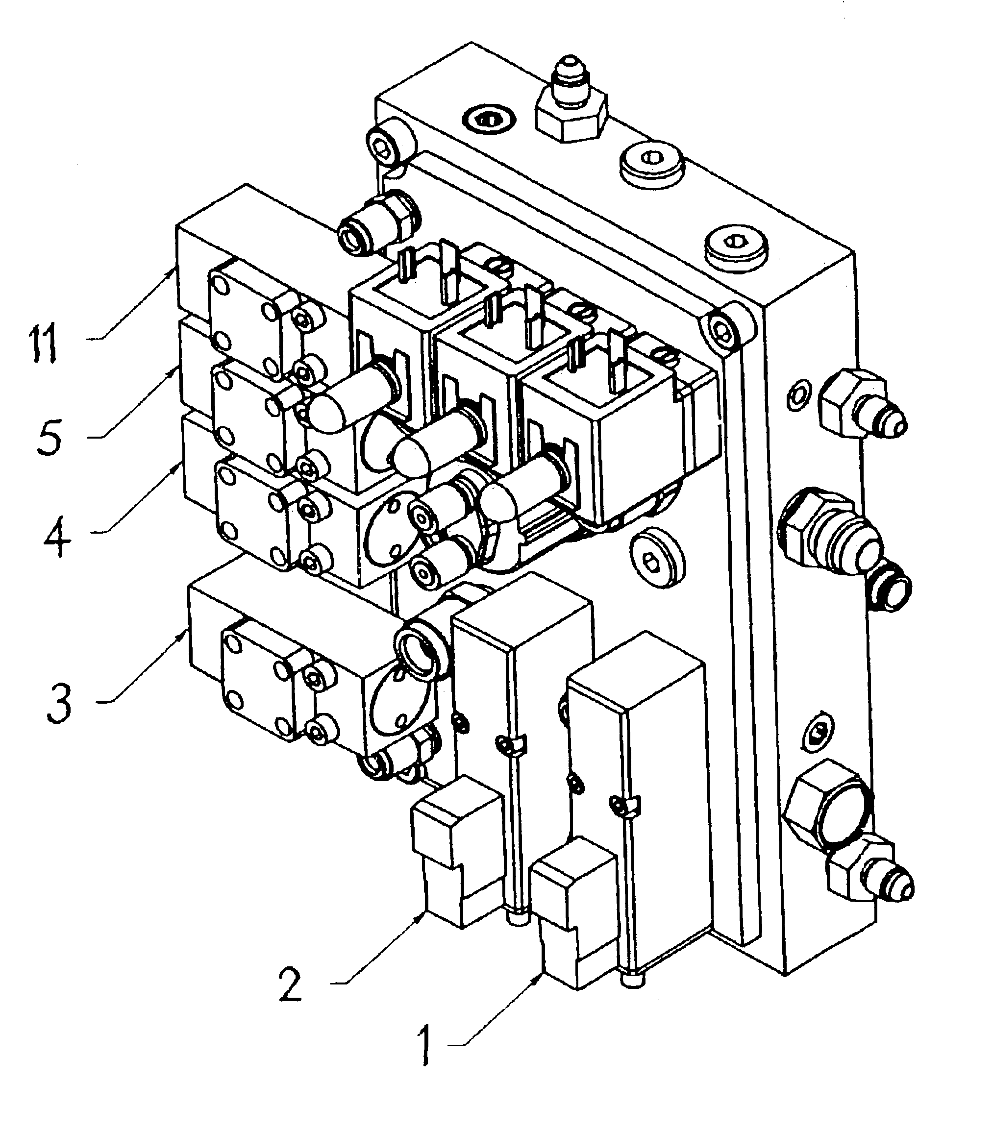
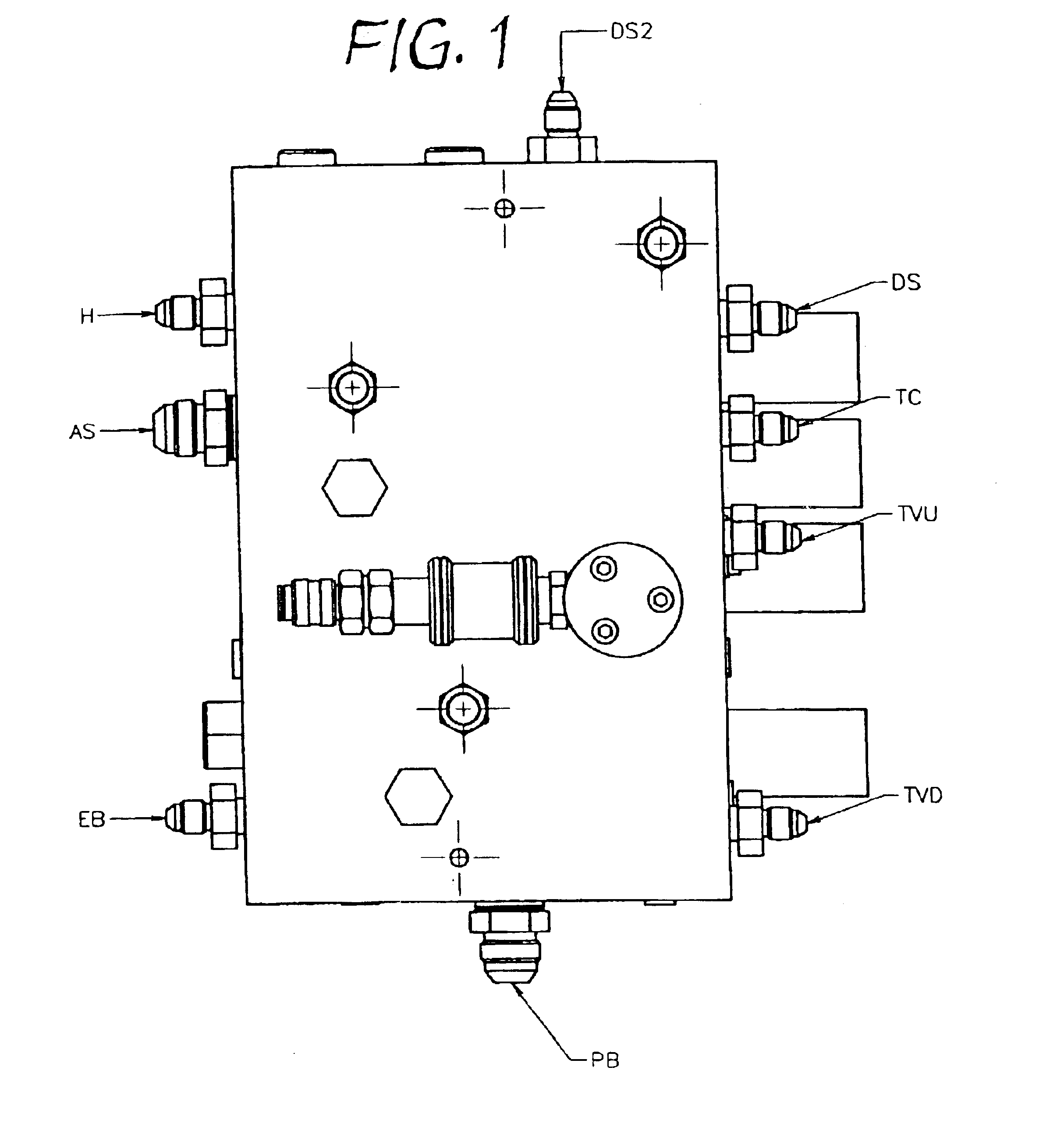
The preferred embodiment is shown in the drawings. It is an example, which can be used for heavy vehicles. It comprises a block B, which is rectangular in its shape, only high quality Swiss aluminium is used to ensure non-porosity. Components are selected from suppliers in Germany, England, Switzerland, Spain and USA. The design uses ISO and other world wide accepted standards to ensure interchange of components from various suppliers.

The integrated pneumatic manifold is machined using a four axis CNC machining centre and modifications can be made in minutes using this system as opposed to injection moulding in which changes can not be made economically. This makes the system suitable for short production runs which are experienced typically in second and third tier industrialized countries and also in some cases in first tier industrialized countries.

The components that are on the protected side of the block include solenoids 1, 2, 6 and 7, pressure switches 3, 4, 5 and 11, pressur...


PUM


Abstract

An integrated pneumatic manifold for installations that require electrical and other components to be separated from a harmful or dangerous environment, in which pneumatic (and / or hydraulic) devices operate, the manifold comprising a block that has drilled into it a large number of passages that are directed in various directions and located at various levels, some passages crossing partially and some wholly with others and cavities machined in various positions. The block has mounting points for components on its surfaces and passive and active pneumatic components are integrated into the cavities and passages of the block. The block serves as a separation between the safe and harmful environments and as a substitution for many passive and active pneumatic components that would normally be individually connected.

Description

The invention lies in the field of pneumatic, hydraulic, electrical and other control systems for vehicles and fixed installations.In conventional practice in electro-pneumatic systems design engineers tend to place pneumatic and electro-pneumatic control components in positions most convenient (e.g. nearest) to the actuators that they control. The benefit of quick reaction times is achieved by use of short pneumatic tubes, which are important in some applications, e.g. in feedback control loops and others where significant response hysteresis is experienced. However, locating pneumatic and electro-pneumatic control components near the actuators that they control often exposes them to a harsh environment.In fixed applications electrical components may not be located in explosive or fiery environments nor in corrosive environments. For example, packaging machinery, which uses pneumatic actuators requires the electrical components to be In an isolated enclosure because spray painting ...

Claims


Application Information

Patent Timeline
Patent Type & Authority Patents(United States)
IPC IPC(8): F15B13/00F15B13/08
CPCF15B13/0814F15B13/0857F15B13/0896F15B13/0892F15B13/0871Y10T137/6892Y10T137/87595Y10T137/87885
Inventor SEYFARTH, OTTO HERMAN
Owner SEYFARTH OTTO HERMAN
Why Eureka
Try Eureka