Method and apparatus of controlling electric vehicle

a technology of electric vehicles and electric motors, applied in the direction of motor/generator/converter stoppers, dynamo-electric converter control, stopping arrangements, etc., can solve the problems of electric vehicles being inconvenient to drive, damage to the teeth of gears, and affecting the efficiency of electric vehicles

Inactive Publication Date: 2004-12-28
MEIDENSHA ELECTRIC MFG CO LTD
View PDF11 Cites 35 Cited by
  • Summary
  • Abstract
  • Description
  • Claims
  • Application Information

AI Technical Summary

Problems solved by technology

Setting the speed reduction gear 5 is responsible for greater capacity of the battery 1, which is also disadvantageous in terms of efficiency as well as energy saving.
Diminishing the gear of the speed reduction gear 5 in size may damage the teeth of the gear.
In this case, the electric vehicle may be inconvenient especially for those who are physically disabled or weak, for the following causes:
Therefore, the damage of the teeth of the gear of the speed reduction gear 5 may cause inability in securing the braking force (torque) of the electromagnetic brake 7.

Method used


Image

  • Method and apparatus of controlling electric vehicle
  • Method and apparatus of controlling electric vehicle
  • Method and apparatus of controlling electric vehicle

Examples


first embodiment

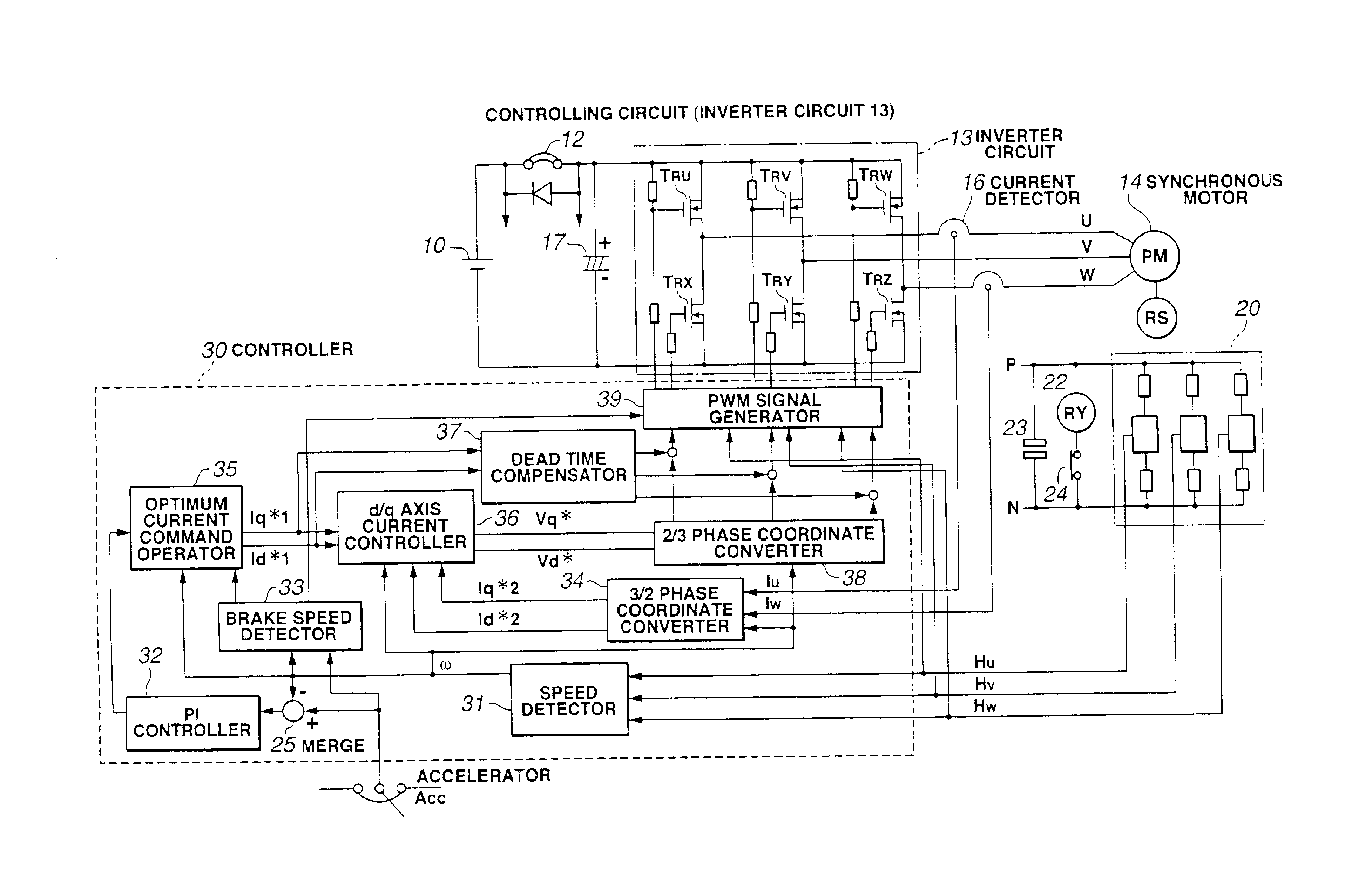
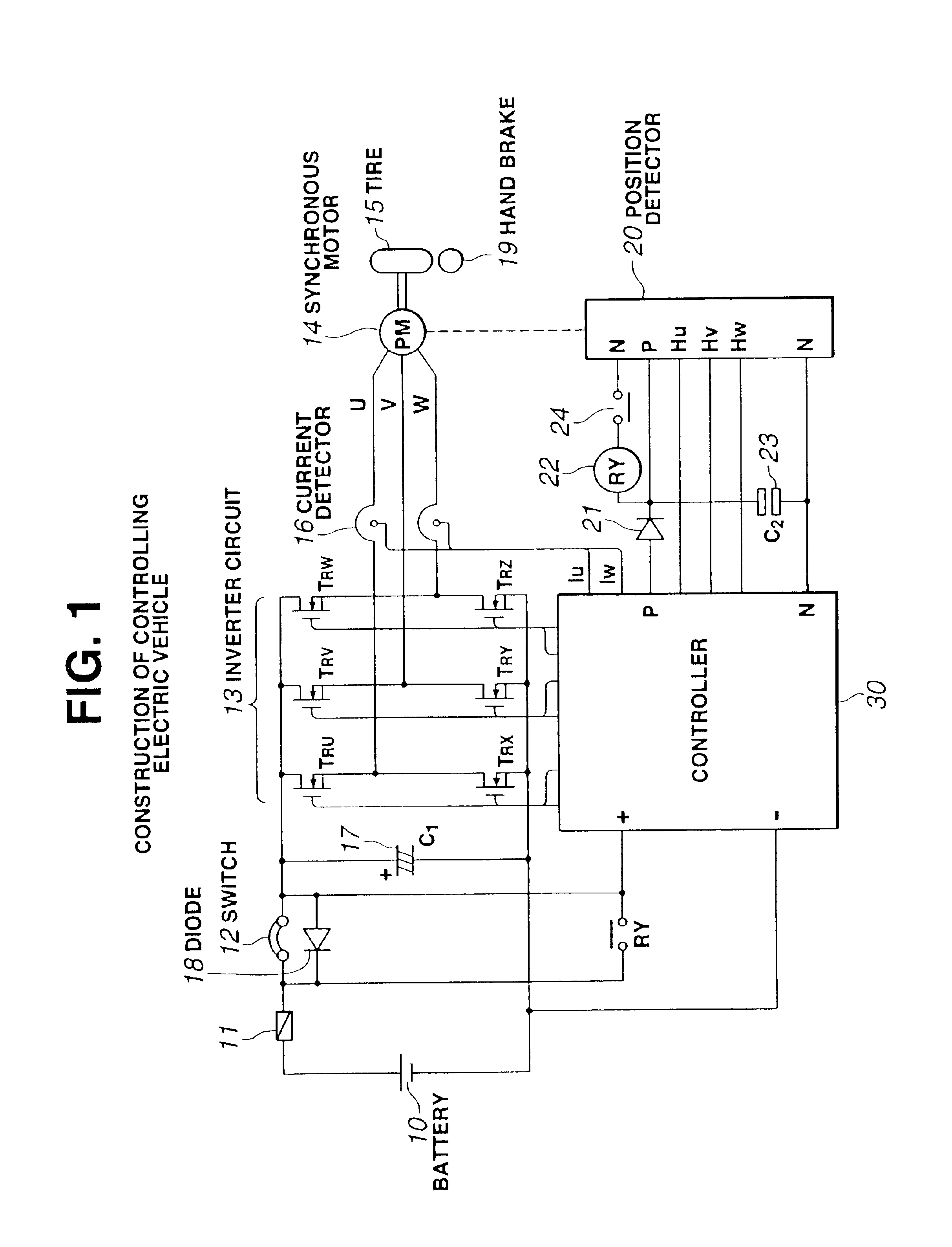
As is seen in FIG. 1, there is provided a construction of an apparatus of controlling an electric vehicle, according to the present invention.

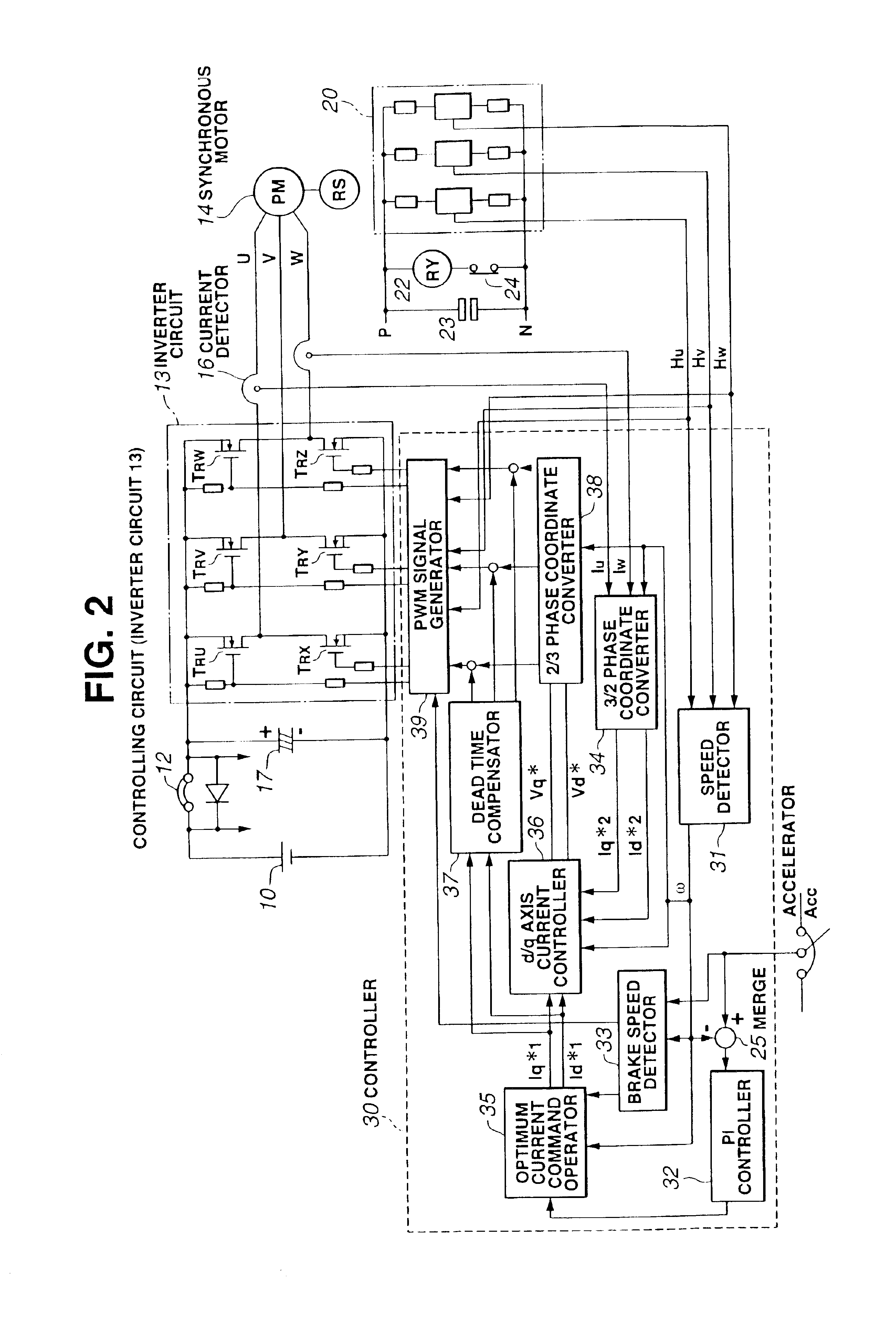
In FIG. 1, a battery 10 acting as a power source connects to an inverter circuit 13 by way of a fuse 11 and a switch 12 (such as breaker, key switch and the like). The inverter circuit 13 is constituted of three phases, including a switching element TRU, a switching element TRV, a switching element TRW, a switching element TRX, a switching element TRY and a switching element TRZ. A first arm connecting the switching element TRU and the switching element TRX has a first bridge contact connecting to a phase terminal U of a synchronous motor 14. A second arm connecting the switching element TRV and the switching element TRY has a second bridge contact connecting to a phase terminal V of the synchronous motor 14. A third arm connecting the switching element TRW and the switching element TRZ has a third bridge contact connecting to a phase terminal...


PUM


Abstract

A method controls an electric vehicle which is so constituted as to drive a synchronous motor by way of a switch and an inverter circuit. A battery acts as a source of driving a controlling power. The synchronous motor has a permanent magnet acting as an outer rotor. The method includes the following operations of:1) detecting that the electric vehicle has an acceleration signal of zero;2) detecting that an actual speed of the electric vehicle is less than a predetermined percent of a rated speed;3) supplying a current to a winding of a fixed phase of the synchronous motor, by way of the inverter circuit; and4) generating a braking force.

Description

1. Field of the InventionThe present invention relates to a method and an apparatus of controlling an electric vehicle.2. Description of the Related ArtFIG. 7 shows a schematic of construction of an electric vehicle in commercial use. A chopper 3 connects to a battery 1 by way of a magnet switch 2. A battery voltage is converted from direct current (hereinafter referred to as "DC") to DC by the chopper. Then, the thus converted voltage is supplied to a direct current motor 4 which is subjected to control. The direct current motor 4 has a rotary shaft connecting to a tire 6 by way of a speed reduction gear 5. Also shown in FIG. 7 includes an electromagnetic brake 7.During travel, the electric vehicle may take the following operations:1. The magnet switch 2 is turned on.2. Conductivity (continuity) of the chopper 3 varies in accordance with an angle of an accelerator (not shown in FIG. 7).3. The voltage applied to the direct current motor 4 varies according to the conductivity of the ...

Claims


Application Information

Patent Timeline
Patent Type & Authority Patents(United States)
IPC IPC(8): B60L11/18A61G5/06A61G5/00A61G5/04B60L7/06H02P6/06H02P6/08H02P6/24
CPCB60L7/003B60L11/1807A61G5/06Y02T10/7258B60L2220/14Y02T10/7005B60L50/60Y02T10/70Y02T10/72
Inventor KAWADA, AKIYOSHIUWABU, TOSHIAKI
Owner MEIDENSHA ELECTRIC MFG CO LTD
Why Eureka
Try Eureka