Direction sensitive and phase-inversion free phase detectors

a detector and direction technology, applied in oscillation comparator circuits, automatic control, instruments, etc., can solve the problem of saving valuable time in the lock-acquisition procedur

Inactive Publication Date: 2004-12-28
TELEFON AB LM ERICSSON (PUBL)
View PDF10 Cites 22 Cited by
  • Summary
  • Abstract
  • Description
  • Claims
  • Application Information

AI Technical Summary

Benefits of technology

In this way, the complementary phase error is properly masked and the phase detector range is effectively reduced to -180.degree.<.theta..sub.e <180.degree., while still maintaining the direction sensitivity. The alternative state trajectory is simply not available any more since the complementary phase error, .theta..sub.ec =360.degree.-.theta..sub.e >180.degree., is larger than half a period, which exceeds the detection range, and is automatically discarded. Consequently, if the phase detector ends up in a state, for example due to reference clock loss, in which the phase error is larger than half a period, the phase detector is shifted back to normal operation with a phase error less than half a period during the next consecutive phase comparison period. Naturally, this saves valuable time in the lock-acquisition procedure.
The phase detector state machine configured with the proposed logic reset state is preferably implemented as a true asynchronous state machine instead of operating with the reset and recovery characteristics of digital flip flops. Designing an asynchronous state machine based on implicitly formed memory elements gives near ideal operation.

Problems solved by technology

Naturally, this saves valuable time in the lock-acquisition procedure.

Method used


Image

  • Direction sensitive and phase-inversion free phase detectors
  • Direction sensitive and phase-inversion free phase detectors
  • Direction sensitive and phase-inversion free phase detectors

Examples


Embodiment Construction

Throughout the drawings, the same reference characters will be used for corresponding or similar elements.

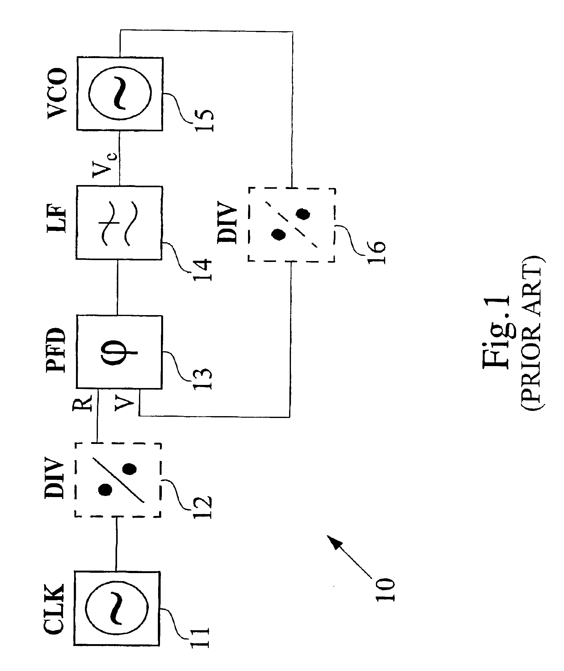
It should be understood that the reference to PLL applications is intended to merely serve as a framework for an understanding of the present invention, and that the invention is not limited thereto. In fact, the phase detectors according to the invention can be used in any type of application where it is desirable to measure a phase difference between two input signals.

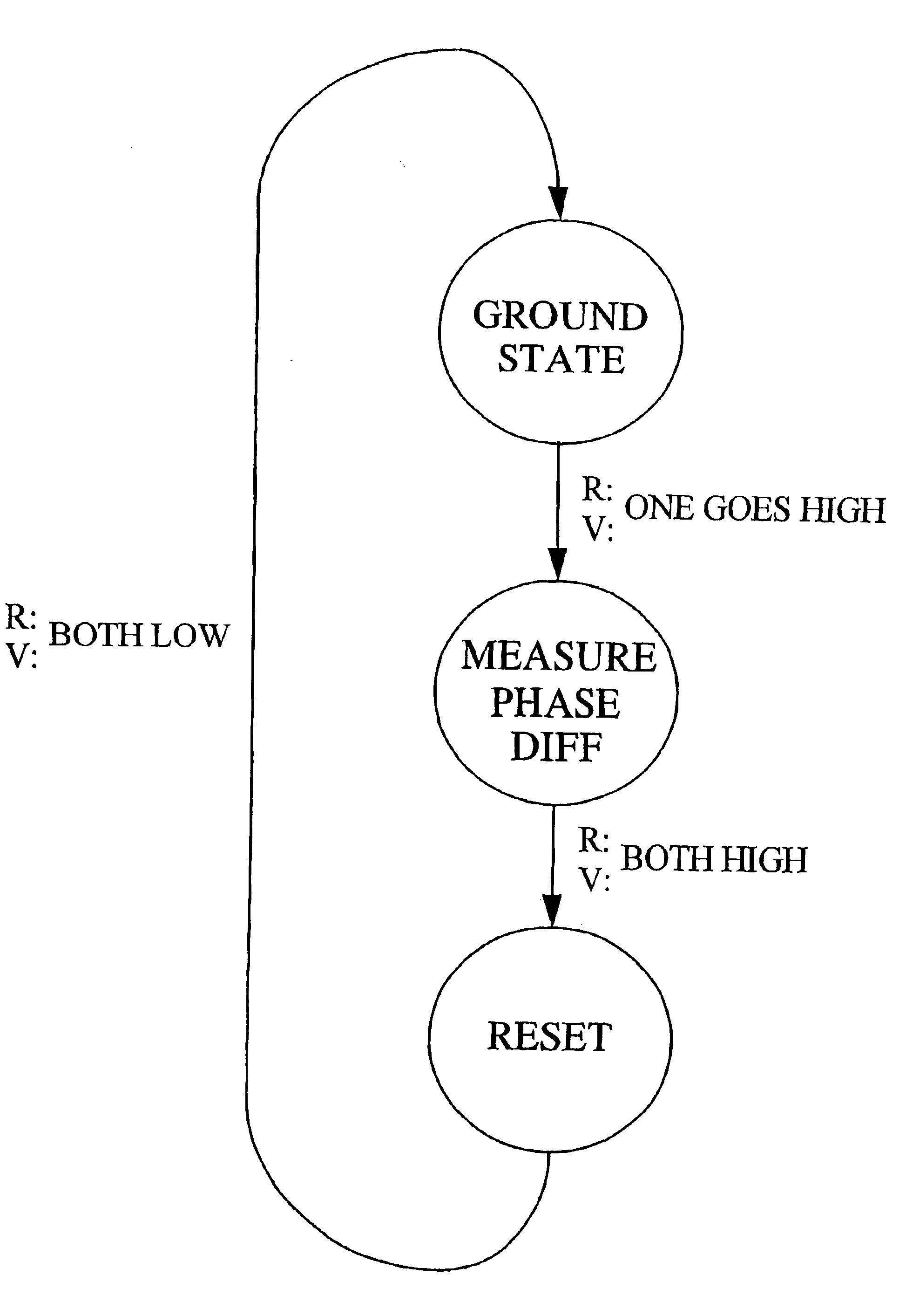
FIG. 5 is a state diagram representation of a state machine for a phase detector according to a general embodiment of the invention. The state diagram is representative of a phase detector state machine triggered by positive edge transitions. The state machine is initially in the ground state, in which both the reference clock R and the loop output clock V are low, waiting for a next positive transition in any of the two phase detector input clocks. As one of the phase detector input clocks R, V goes high the sta...


PUM


Abstract

The invention relates to a new phase detector state machine having a reset state that is released only when both phase detector input signals (R, V) have a common predetermined signal state. In this way, phase inversion is effectively prevented. The complementary phase error is properly masked and the phase detector range is reduced to the interval-180°<THETAe<180°, while still maintaining the direction sensitivity. Phase errors thetae larger than half a period are automatically discarded. Consequently, if the phase detector ends up in a state, for example due to reference clock loss, in which the phase error is larger than half a period, the phase detector will be shifted back to normal operation with a phase error less than half a period during the next consecutive phase comparison period. Naturally, this saves valuable time in the lock-acquisition procedure.

Description

The present invention generally relates to phase detectors, and more specifically to direction sensitive phase detectors.Phase detectors are found in numerous applications of all modern technologies. They are widely used in areas of electronics and in different fields of communication, in particular the field of telecommunication.Basically, a phase detector is an arrangement for measuring a phase difference between two input signals. In a typical application, the phase detector is used in a phase-locked loop (PLL). A phase-locked loop is generally a circuit for synchronizing an output signal of the loop with an input reference signal in frequency as well as in phase, and it is often used in retiming and frequency synthesization applications. In order to accomplish the synchronization of the reference signal and the loop output signal, a phase detector is required for continuously measuring the phase difference between the two signals, and the measured phase difference is utilized fo...

Claims


Application Information

Patent Timeline
Patent Type & Authority Patents(United States)
IPC IPC(8): H03L7/089H03D13/00H03L7/08
CPCH03L7/089H03D13/004
Inventor FREDRIKSSON, JESPER
Owner TELEFON AB LM ERICSSON (PUBL)
Why Eureka
Try Eureka