
Capacitance manometer having a relatively thick flush diaphragm under tension to provide low hysteresis

a technology of flush diaphragm and manometer, which is applied in the direction of fluid pressure measurement using capacitance variation, instruments, measurement devices, etc., can solve the problems of low output value, increased errors, and cdgs without flush diaphragms that are generally not convertible to be used

Inactive Publication Date: 2005-01-04
S TEC INC
View PDF32 Cites 29 Cited by
  • Summary
  • Abstract
  • Description
  • Claims
  • Application Information

AI Technical Summary

Benefits of technology

Embodiments in accordance with the present invention provide a capacitance diaphragm gauge (CDG) having a flush diaphragm with low hysteresis characteristics. The CDG has a simple structure that can be repeatably manufactured in an affordable manner.
Further embodiments in accordance with the present invention include a second electrode positioned proximate to the perimeter of the diaphragm to compensate for the expansion of the space between the electrode and the diaphragm by providing a second capacitance measurement signal that can be processed to cancel out the effect of the expansion.

Problems solved by technology

On the other hand, a CDG that does not have flush diaphragm generally is not convertible to be used in applications requiring a flush diaphragm device because the outer support structures for the diaphragm extend beyond the pressure face of the diaphragm.
Although the same output value should be generated for the given pressure irrespective of the previous pressure, hysteresis effects may cause the output value to be too high when the given pressure is approached from a higher pressure and may cause the output value to be to low when the given pressure is approached from a lower pressure.
Abnormal excursions can cause greater errors.
Since hysteresis errors depend at least in part on the magnitude of the pressure excursions, the hysteresis errors are usually unpredictable and are therefore major concerns.
One problem with high pressure measuring devices is to keep the deflection small enough by having a pretension carrying the load.
Many techniques have been used to pretension diaphragms, particularly for diaphragms in low pressure CDGS; however, the techniques used for high pressure diaphragms have proven to be very limited, and as the devices have become smaller, the techniques have become even more limited.
This technique causes the whole fixture to become hot and thus causes a significant uncertainty in results as sequential units are processed.
Such a technique also presents problems in maintaining good thermal contact between the diaphragm and the platen, which again causes the resulting tension on the diaphragm to be nonrepeatable.
Forming the shim as part of the CDG body is a very expensive and unrepeatable way to obtain the spacing between the diaphragm and the electrode.
Therefore, the shim needs to be extremely hard.
The heat-treating may cause the part to warp and to lose the spacing accuracy that is required for precision measurements.

Method used


Image

  • Capacitance manometer having a relatively thick flush diaphragm under tension to provide low hysteresis
  • Capacitance manometer having a relatively thick flush diaphragm under tension to provide low hysteresis
  • Capacitance manometer having a relatively thick flush diaphragm under tension to provide low hysteresis

Examples


Embodiment Construction

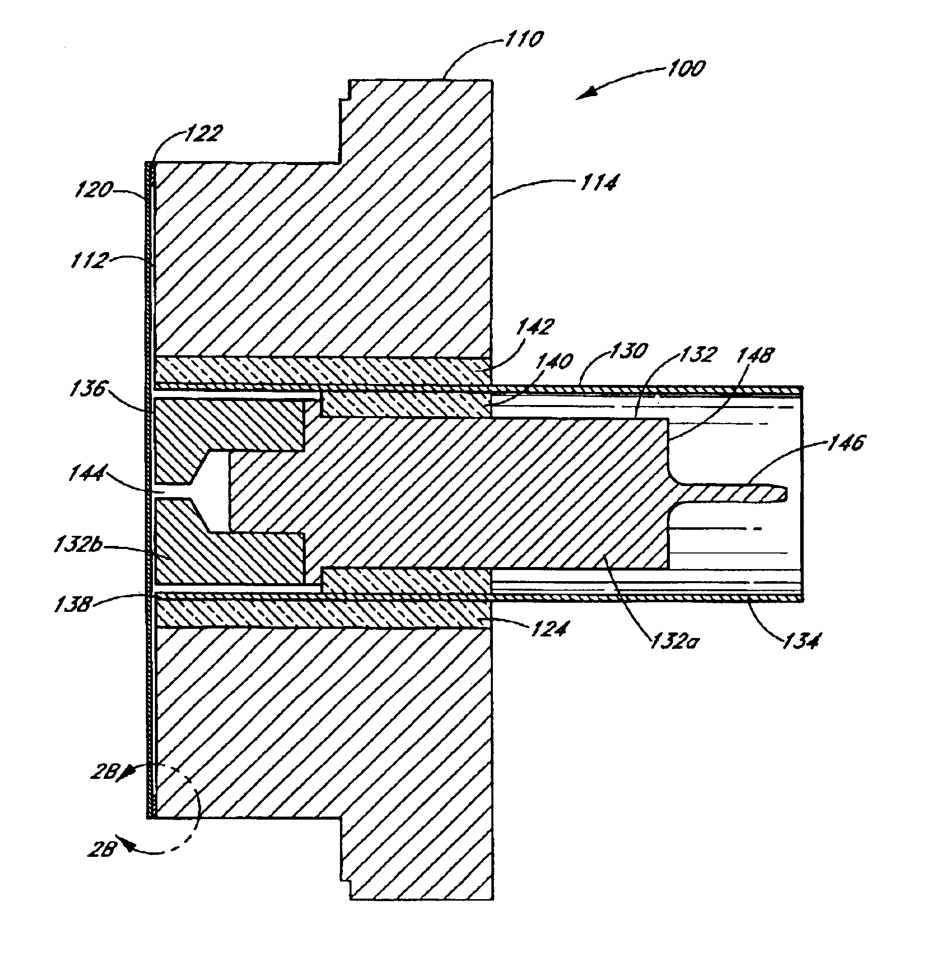
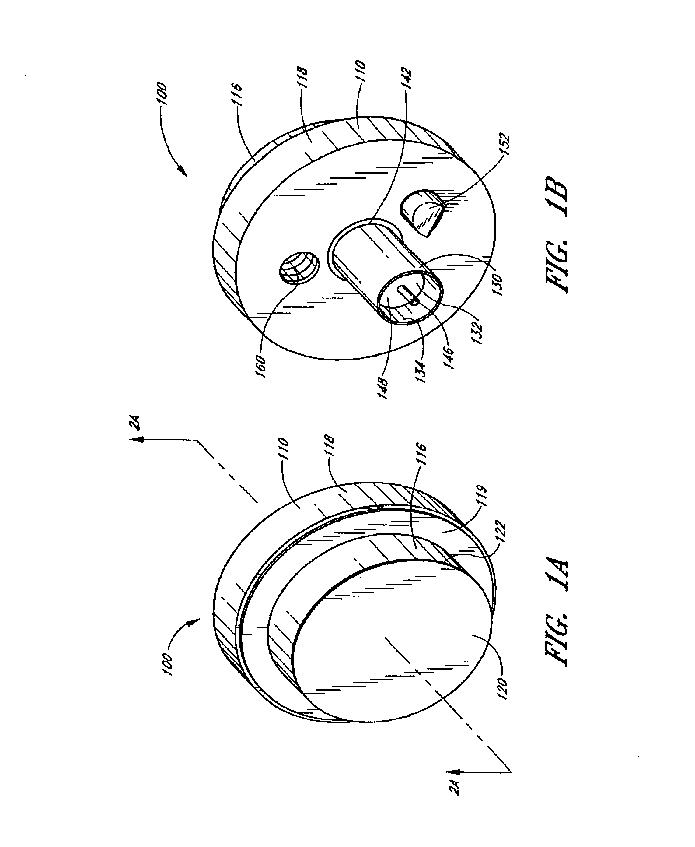
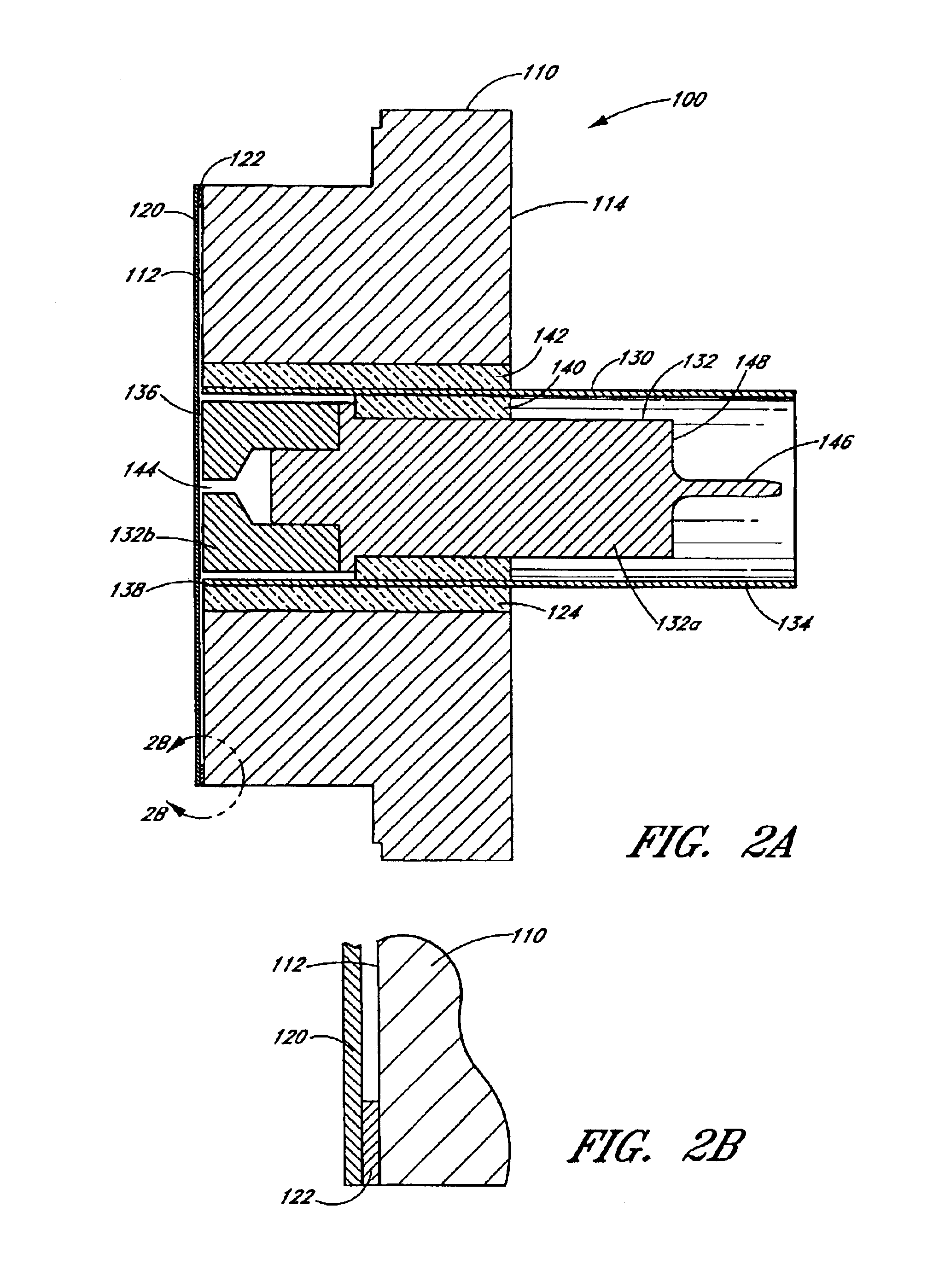
FIGS. 1A, 1B, 2A, 2B, 3 and 4 illustrate an embodiment of a capacitance diaphragm gauge (CDG) 100. As shown in FIG. 1A, the CDG 100 includes a body structure 110, having a front surface 112 (see FIG. 4) and a rear surface 114 (see FIG. 4). In the embodiments illustrated herein, body structure 110 is generally cylindrical, and the front surface 112 and the rear surface 114 have circular shapes. In the preferred embodiments, the area of the front surface 112 is smaller than the area of the rear surface 114, and a forward cylindrical portion 116 of the body structure 110 proximate to the front surface 112 has a smaller diameter than a rearward cylindrical portion 118 proximate to the rear surface 114 such that the body structure 110 has a stepped transition from the front portion 116 to the rear portion 118 that forms a lip 119 around the front portion 116. The lip 119 may be used when mounting the CDG 100 in certain applications.

A flush diaphragm 120 is mounted proximate to the front ...


PUM

PropertyMeasurementUnit
thicknessaaaaaaaaaa
thicknessaaaaaaaaaa
diameteraaaaaaaaaa

Abstract

A capacitance diaphragm gauge (CDG) for measuring pressure includes a flush diaphragm mounted to a body structure via a shim or other raised perimeter portion. The diaphragm and the shim are welded to the body structure while the diaphragm is maintained at an elevated temperature. Contraction of the diaphragm as it cools pretensions the diaphragm to substantially reduce hysteresis effects. An electrode advantageously includes two portions with one portion providing excellent bonding characteristics and the other portion having temperature characteristics corresponding to the body structure and the diaphragm. An alternative CDG includes two identical electrodes with a first electrode positioned proximate to the center of the diaphragm and with a second electrode positioned proximate to the perimeter of the diaphragm. The second electrode provides a second capacitance signal that is used to compensate for changes in capacitance between the diaphragm and the first electrode caused by temperature changes.

Description

BACKGROUND OF INVENTION1. Field of the InventionThe present invention is in the field of pressure transducers having a variable capacitance between a diaphragm exposed to the pressure and a fixed electrode.2. Description of the Related ArtCapacitance diaphragm gauges (CDGs) have been used for many years to measure pressures. CDGs are particularly useful for measuring very low pressures (e.g., much lower than atmospheric pressure) such as pressures in an evacuated system (e.g., a semiconductor fabrication system). A CDG produces an electrical output that represents a measure of a pressure input with respect to a reference pressure.Basically, an exemplary CDG includes at least one electrode that is supported on a suitable support structure. The electrode is positioned in close proximity to a flexible diaphragm in a sealed and evacuated cavity. The diaphragm is positioned in the device so that one face of the diaphragm (the pressure face) is exposed to an unknown pressure to be measure...

Claims


Application Information

Patent Timeline
Patent Type & Authority Patents(United States)
IPC IPC(8): G01L9/12G01L9/00H01L
CPCG01L9/0072G01L9/12
Inventor FERRAN, ROBERT J.ROHRBACH, DANIEL M.OSWALD, MICHAEL
Owner S TEC INC
Learn More