Engine valve actuator assembly with automatic regulation

Inactive Publication Date: 2005-01-04
GM GLOBAL TECH OPERATIONS LLC
View PDF20 Cites 5 Cited by
  • Summary
  • Abstract
  • Description
  • Claims
  • Application Information

AI Technical Summary

Benefits of technology

One advantage of the present invention is that a valve actuator assembly is provided for an engine that has hydraulic feedback for precise motion by self-regulating flow control. Another advantage of the present invention is that the valve actuator assembly has controllability that is open loop stable with automatic regulation. Yet another advantage of the present invention is that the valve actuator assembly is an enabler for improved valve train stability without sacrificing dynamic performance. Still another advantage of the present invention is that the valve actuator assembly is an enabler for improved engine performance, improved engine fuel economy by lowering fuel consumption and improved engine emissions by lowering emissions. A further advantage of the present invention is that the valve actuator assembly minimizes energy consumption by self-regulation flow control, simple spool valves, and efficient valve control to minimize throttling of the fluid flow. Yet a further advantage of the present invention is that the valve actuator assembly has uses one solenoid, one on / off valve, and two spool valves. Still a further advantage of the present invention is that the valve actuator assembly has a relatively small size and is easy to package in an engine. Another advantage of the present invention is that the valve actuator assembly has a relatively low cost. Yet another advantage of the present invention is that the valve actuator assembly has improved output torque and built-in soft landing capability to reduce noise and improve durability. A further advantage of the present invention is that the valve actuator assembly has independent control over the first and second spool valves for improved dynamic response.
is that a valve actuator assembly is provided for an engine that has hydraulic feedback for precise motion by self-regulating flow control. Another advantage of the present invention is that the valve actuator assembly has controllability that is open loop stable with automatic regulation. Yet another advantage of the present invention is that the valve actuator assembly is an enabler for improved valve train stability without sacrificing dynamic performance. Still another advantage of the present invention is that the valve actuator assembly is an enabler for improved engine performance, improved engine fuel economy by lowering fuel consumption and improved engine emissions by lowering emissions. A further advantage of the present invention is that the valve actuator assembly minimizes energy consumption by self-regulation flow control, simple spool valves, and efficient valve control to minimize throttling of the fluid flow. Yet a further advantage of the present invention is that the valve actuator assembly has uses one solenoid, one on / off valve, and two spool valves. Still a further advantage of the present invention is that the valve actuator assembly has a relatively small size and is easy to package in an engine. Another advantage of the present invention is that the valve actuator assembly has a relatively low cost. Yet another advantage of the present invention is that the valve actuator assembly has improved output torque and built-in soft landing capability to reduce noise and improve durability. A further advantage of the present invention is that the valve actuator assembly has independent control over the first and second spool valves for improved dynamic response.

Problems solved by technology

However, this type of valve actuation introduces constraints on valve operation that preclude optimal valve opening and closing schedules, compromising engine performance, fuel economy, and emissions.
One disadvantage of some camless valve trains is their poor controllability due to open loop instability, which causes great difficulty in their operation.
Another disadvantage of some camless valve trains is that they do not provide full capability for variable lift.
Further disadvantages of some camless valve trains are that they have relatively high cost, large size, high energy consumption, low repeatability from cycle to cycle and cylinder to cylinder, hard seating impact, and high seating velocity induced noise.

Method used


Image

  • Engine valve actuator assembly with automatic regulation
  • Engine valve actuator assembly with automatic regulation
  • Engine valve actuator assembly with automatic regulation

Examples


Embodiment Construction

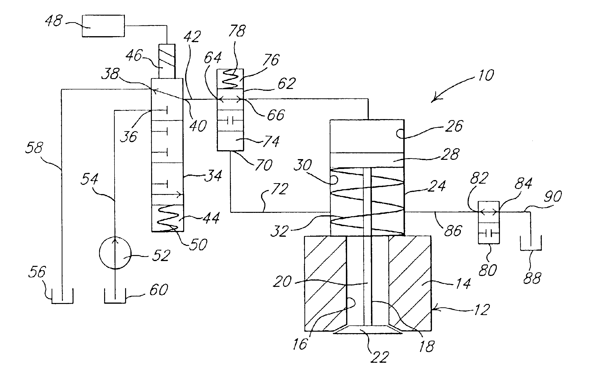
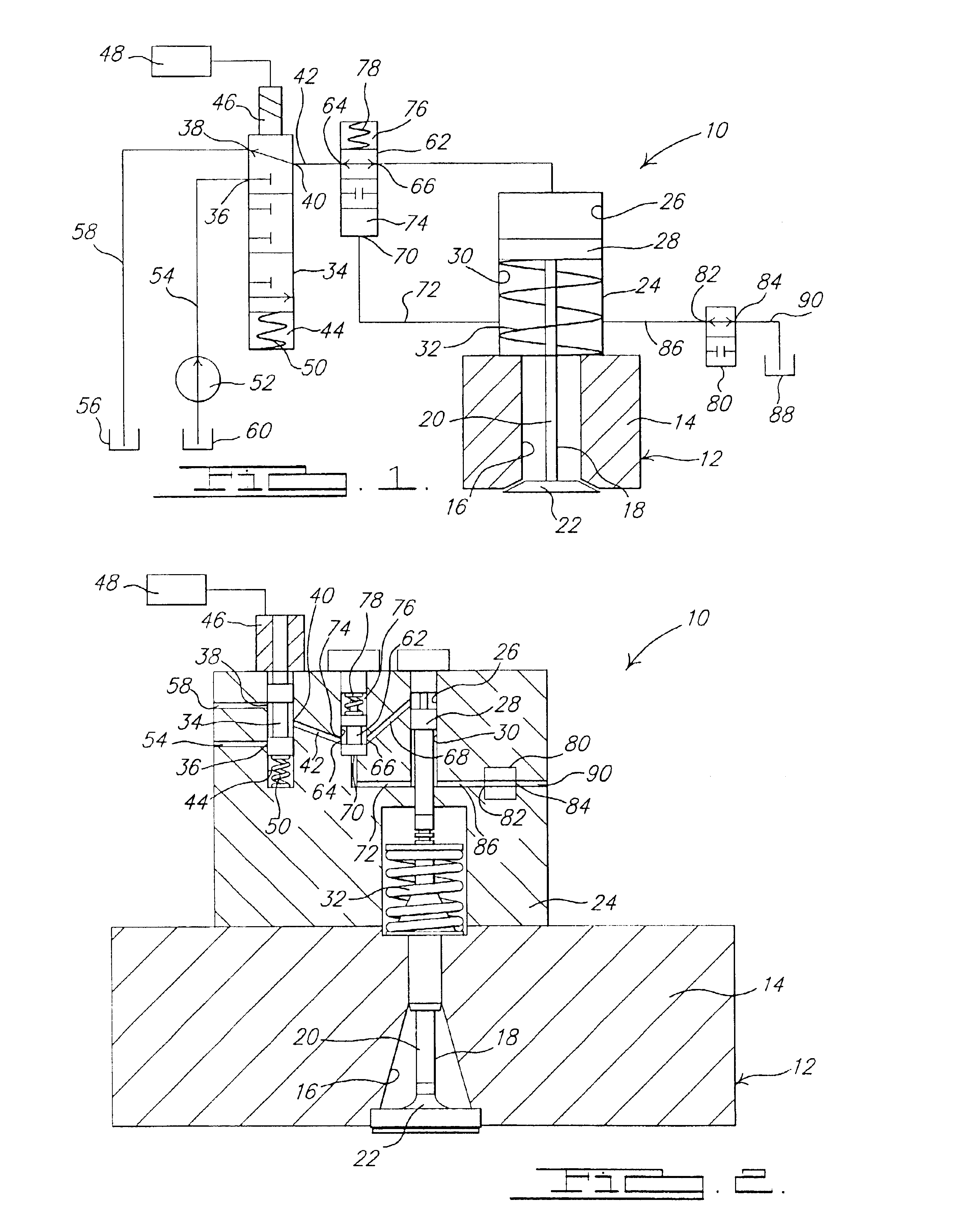
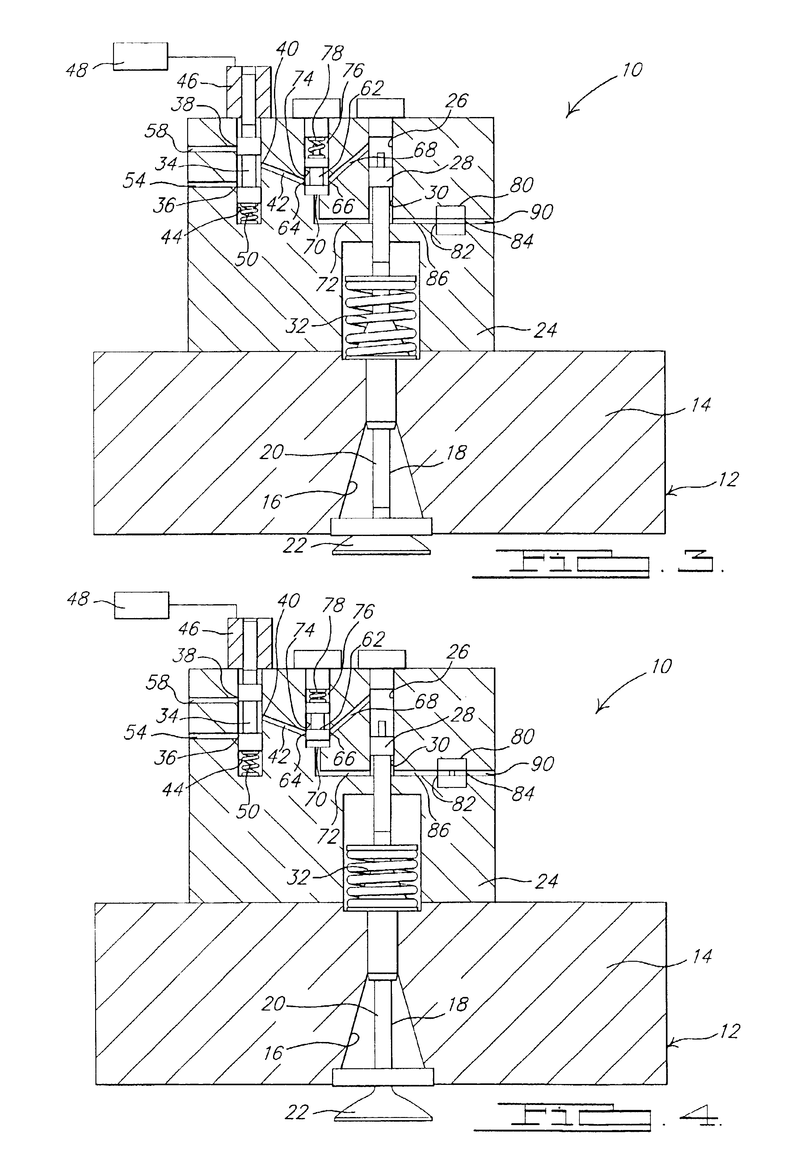
Referring to the drawings and in particular FIG. 1, one embodiment of a valve actuator assembly 10, according to the present invention, is shown for an engine, generally indicated at 12, of a vehicle (not shown). The engine 12 is of an internal combustion type. The engine 12 includes an engine block 14 having at least one opening 16 therein in communication with at least one internal combustion chamber (not shown). The engine 12 also includes a movable engine valve 18 for each opening 16. The engine valve 18 has a valve stem 20 and a valve head 22 at one end of the valve stem 20. The engine valve 18 is movable to open and close its respective opening 16 between an open position as illustrated in FIGS. 3 and 4 and a closed position as illustrated in FIG. 2. It should be appreciated that the engine valve 18 may be either an intake or exhaust valve. It should also be appreciated that the valve actuator assembly 10 is a camless valve train for the engine 12. It should further be appreci...


PUM


Abstract

A valve actuator assembly for an engine includes a movable engine valve, a movable first spool valve, and a movable second spool valve. The valve actuator assembly also includes a driving channel interconnecting the second spool valve and the engine valve, an intermediate channel interconnecting the first spool valve and the second spool valve, and a feedback channel interconnecting the second spool valve and the engine valve. The valve actuator assembly includes an actuator operatively cooperating with the first spool valve to position the first spool valve to prevent and allow fluid flow in and out of the second spool valve and the driving channel to position the engine valve. The valve actuator assembly further includes an on / off valve in fluid communication with the feedback channel to enable and disable the feedback channel to control motion of the second spool valve.

Description

TECHNICAL FIELDThe present invention relates generally to intake or exhaust valve actuators for engines and, more particularly, to a valve actuator assembly with automatic regulation for an internal combustion engine.BACKGROUND OF THE INVENTIONIt is known to provide a valve train or valve actuator assembly for an engine such as an internal combustion engine of a vehicle such as a motor vehicle. Typically, the valve train includes one or more valves, a cam shaft having at one or more cams, and a tappet contacting each cam and valve. Typically, engine valve actuation is accomplished via the engine-driven camshaft. However, this type of valve actuation introduces constraints on valve operation that preclude optimal valve opening and closing schedules, compromising engine performance, fuel economy, and emissions.It is also known to provide a camless valve train for an internal combustion engine. An example of such a camless valve train is disclosed in the prior art. For example, a camle...

Claims


Application Information

Patent Timeline
IPC IPC(8): F01L9/02F01L9/00F01L9/10
CPCF01L9/02F01L9/10
Inventor SUN, ZONGXUAN
Owner GM GLOBAL TECH OPERATIONS LLC
Why Eureka
Try Eureka