Sensor failure diagnostic apparatus

Active Publication Date: 2018-09-27
DENSO CORP
View PDF2 Cites 4 Cited by
  • Summary
  • Abstract
  • Description
  • Claims
  • Application Information

AI Technical Summary

Benefits of technology

The patent text aims to provide a sensor failure diagnostic apparatus for detecting intermediate value failures of sensors used to monitor the characteristics of fuel supplied to a combustion system. The apparatus can improve combustion control and reduce emissions and fuel consumption by adjusting target values based on the fuel's characteristic.

Problems solved by technology

However, it is difficult to diagnose the intermediate value failure of the characteristic sensor.

Method used


Image

  • Sensor failure diagnostic apparatus
  • Sensor failure diagnostic apparatus
  • Sensor failure diagnostic apparatus

Examples


first embodiment

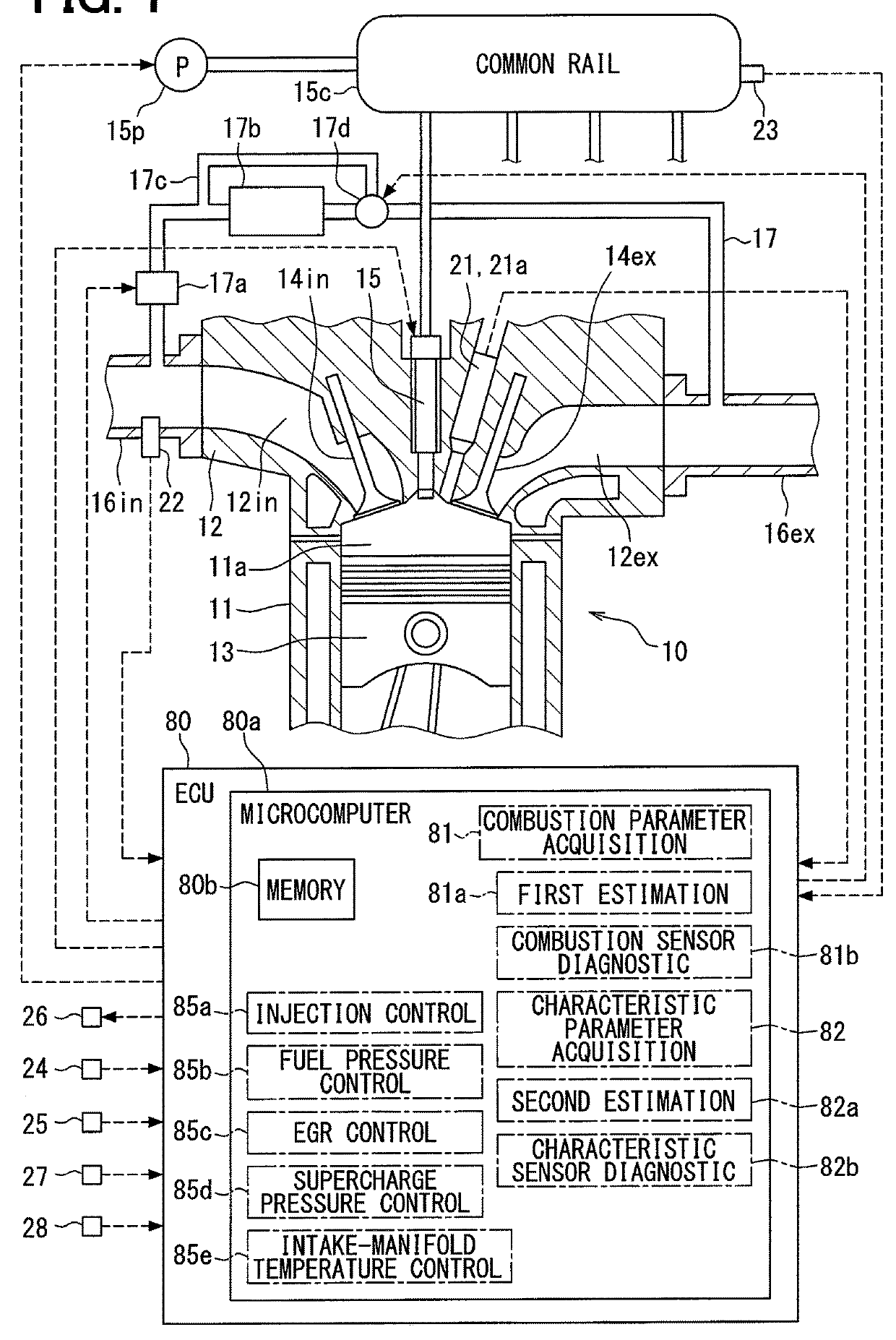
[0035]According to an embodiment of the present disclosure, a sensor failure diagnostic apparatus is constituted based on an electric control unit (ECU) 80 shown in FIG. 1. The ECU 80 includes a microcomputer 80a, an input processing circuit that is not shown, and an output processing circuit that is not shown. The microcomputer 80a includes a central processing unit (CPU) that is not shown and a memory 80b. Since the CPU executes a specified program stored in the memory 80b, the microcomputer 80a controls operations of a fuel injector 15, a fuel pump 15p, an exhaust gas recirculation (EGR) valve 17a, a temperature regulating valve 17d, and a supercharge pressure-regulating apparatus 26 which are included in the combustion system. A combustion state in an internal combustion engine 10 included in the combustion system is controlled in a required state by the above controls. The combustion system and the ECU 80 are mounted to a vehicle, and the vehicle travels by using an output of t...

second embodiment

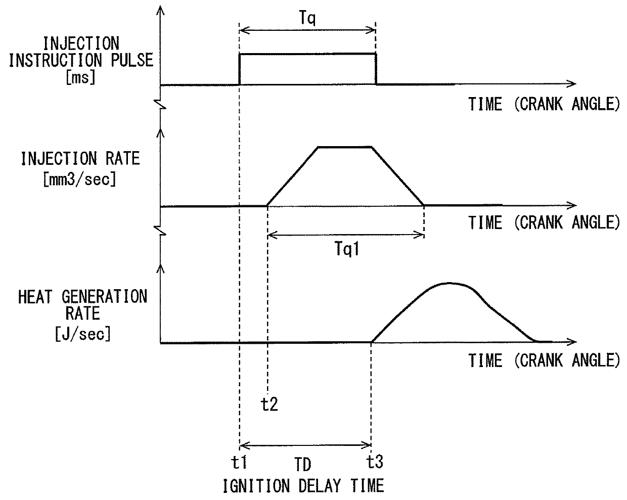
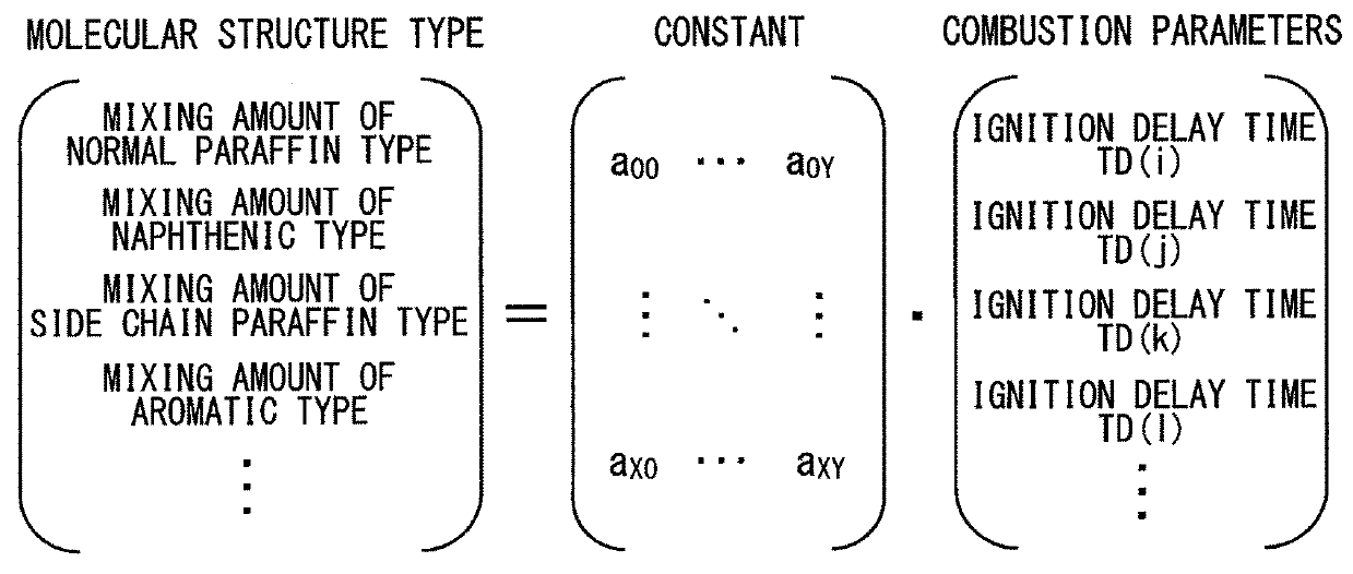
[0099]According to the present embodiment, a characteristic sensor failure diagnostic processing shown in FIG. 13 is replaced by a characteristic sensor failure diagnostic processing shown in FIG. 14. In the characteristic sensor failure diagnostic processing shown in FIG. 13, the microcomputer 80a determines whether the characteristic sensor has failed by comparing the mixing ratio (first estimation value X1) estimated by the first estimation unit 81a based on the combustion parameter with the mixing ratio (second estimation value X2) estimated by the second estimation unit 82a based on the characteristic parameter. According to the present embodiment, as shown in FIG. 14, the microcomputer 80a estimates the characteristic parameter based on the combustion parameter sensed by the combustion sensor, determines whether the characteristic sensor had failed by comparing an estimated value of the characteristic parameter with the characteristic parameter sensed by the characteristic sen...


PUM


Abstract

A sensor failure diagnostic apparatus includes a first estimation unit to estimate a mixing ratio of each type of a molecular structure included in a fuel, based on combustion parameters when a combustion of an internal combustion engine is executed in different combustion conditions, among the combustion parameters sensed by a combustion sensor, a second estimation unit to estimate the mixing ratio, based on characteristic parameters sensed by a characteristic sensor, a combustion sensor diagnostic unit to determine whether a failure of the combustion sensor exists, based on a sensed value of the combustion sensor when the combustion is not executed, and a characteristic sensor diagnostic unit to determine whether a failure of the characteristic sensor exists, by comparing the mixing ratio estimated by the first estimation unit with the mixing ratio estimated by the second estimation unit when the combustion sensor diagnostic unit determines the combustion sensor is normal.

Description

CROSS REFERENCE TO RELATED APPLICATION[0001]This application is based on Japanese Patent Application No. 2015-228272 filed on Nov. 23, 2015, the disclosure of which is incorporated herein by reference.TECHNICAL FIELD[0002]The present disclosure relates to a sensor failure diagnostic apparatus which diagnoses whether a failure of a sensor included in a combustion system occurs.BACKGROUND ART[0003]Conventionally, when controlling an operation of a combustion system including an internal combustion engine, it is known that a sensor (combustion sensor) senses a combustion state of the internal combustion engine and a sensed value is used in a next combustion control. For example, a cylinder pressure sensor (combustion sensor) senses a pressure in a combustion chamber. A variation of an ignition time point or a variation of a heat generation rate is estimated based on a sensed result, and then target values of an injection amount of the fuel, an injection time point of the fuel, an EGR a...

Claims


Application Information

Patent Timeline
IPC IPC(8): G01M15/02G01M15/04G01M15/08G01M15/11
CPCG01M15/02G01M15/042G01M15/048G01M15/08G01M15/11F02D41/222F02B77/085F02D2200/0611F02D35/023F02D35/028F02D19/0623F02D19/0634F02M26/25F02B77/04Y02T10/40Y02T10/30
Inventor OKABAYASHI, ATSUNORIHOSHI, SHINYA
Owner DENSO CORP
Why Eureka
Try Eureka