Liquid flow control valve

a flow control and valve body technology, applied in the direction of functional valve types, gas/liquid distribution and storage, structural/machine measurement, etc., can solve the problem of high flow volume, and achieve the effect of minimising water wastage and minimising wastag

Inactive Publication Date: 2005-01-04
SAINT WILLIAM HENRY
View PDF7 Cites 72 Cited by
  • Summary
  • Abstract
  • Description
  • Claims
  • Application Information

AI Technical Summary

Benefits of technology

It is a principal aim of the present invention to provide a control valve which permits the detection of such abnormal conditions and then takes remedial action in order to minimise water wastage. Moreover, it is a further aim to provide a method of performing these functions, again to minimise wastage.
In a modified form of the valve, there is provided a temperature sensor adapted to monitor the temperature of water passing through the valve. If the temperature of that water falls below some pre-set value, such as 2° C., a warning alarm may be given. If the temperature falls yet lower, the valve may be closed to prevent possible leakage of water through a burst pipe.

Problems solved by technology

Such an abnormal condition may be an excessive flow-rate, leading to a high flow volume over a protracted period, or it may be a lesser flow rate but for an unusually long period.

Method used


Image

  • Liquid flow control valve
  • Liquid flow control valve
  • Liquid flow control valve

Examples


Embodiment Construction

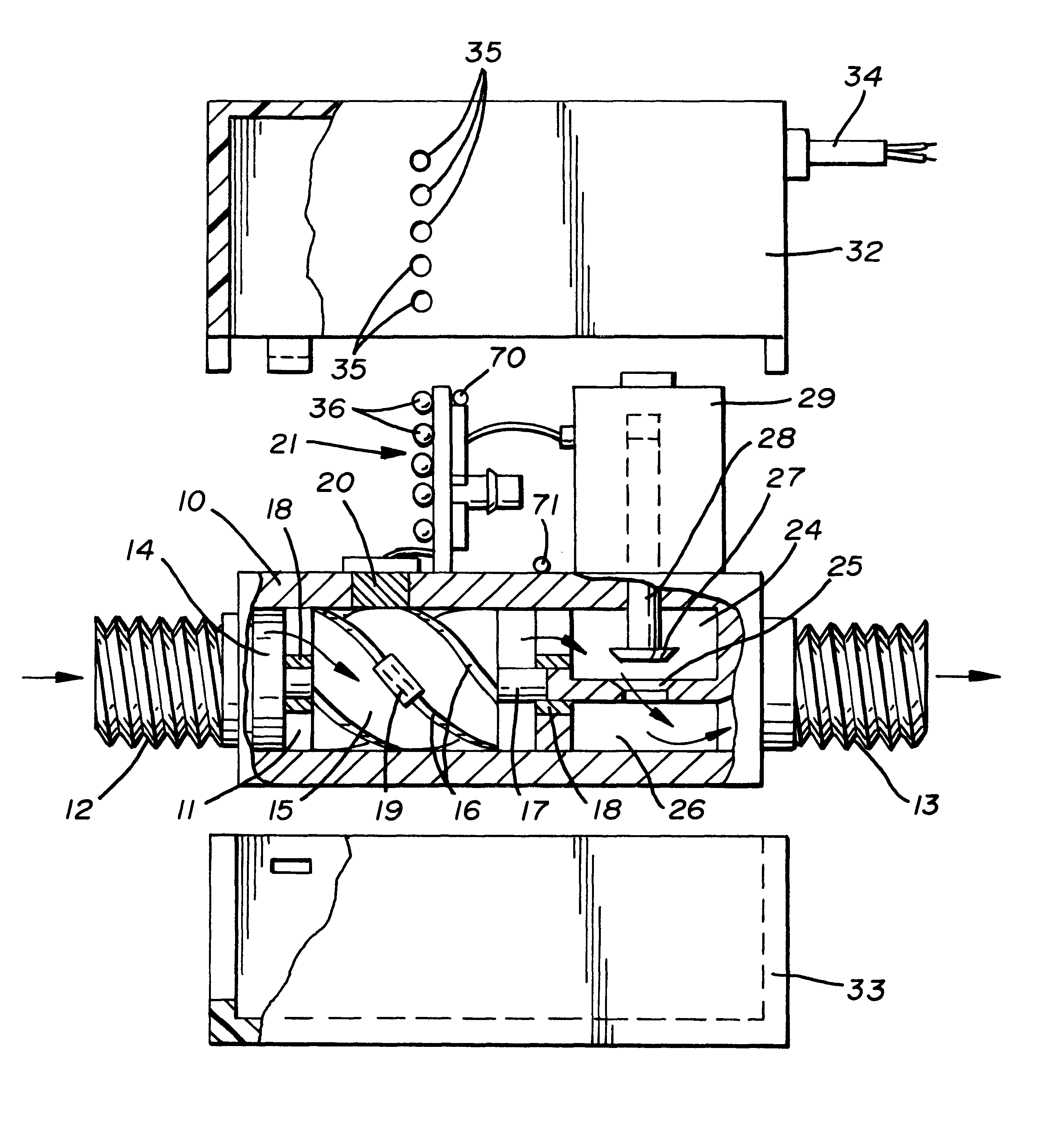
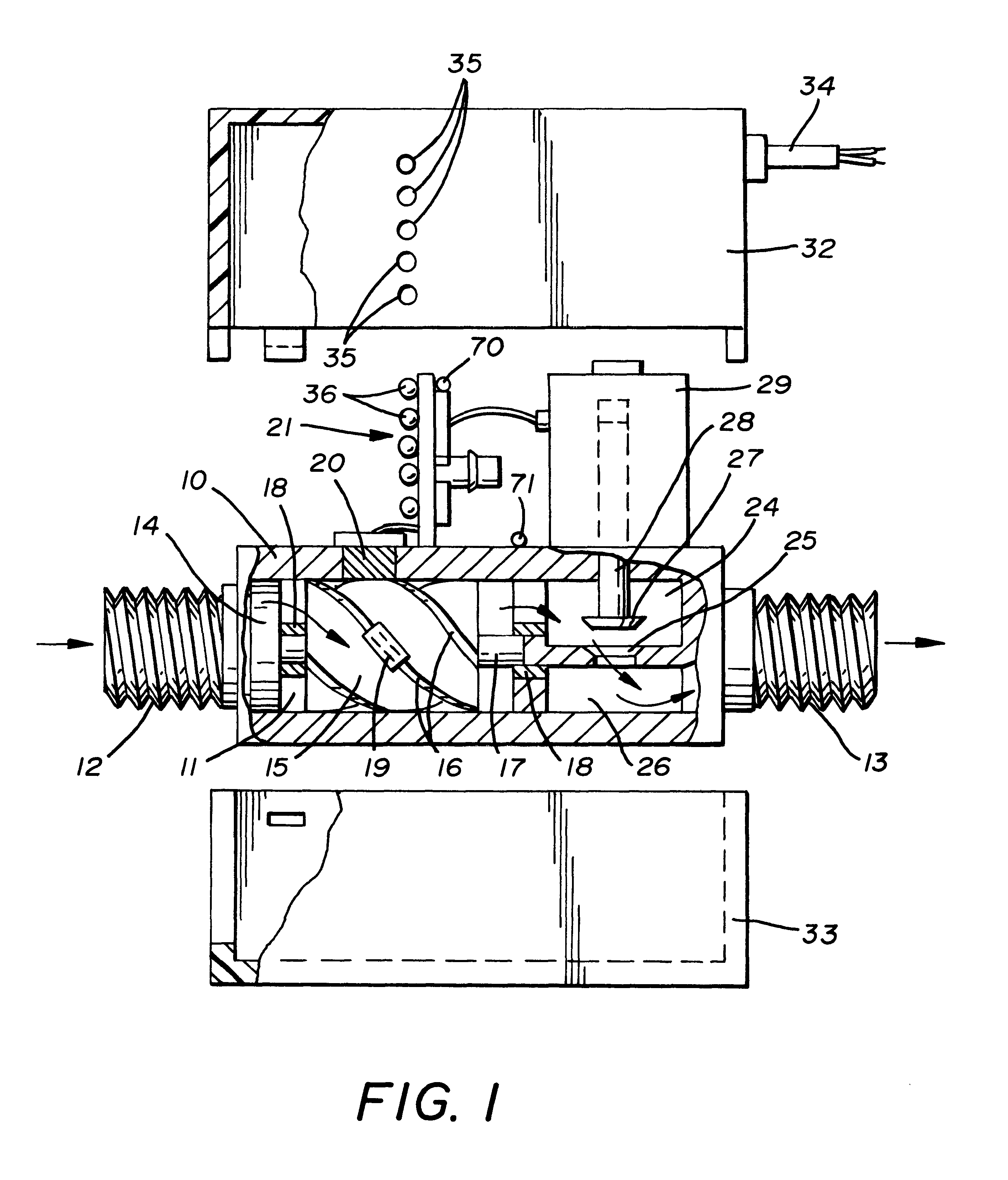
Referring initially to FIG. 1, the fluid flow control valve comprises a valve body 10 defining a fluid flow passageway 11 therethrough. At the two ends of the passageway 11, there are provided inlet and outlet threaded connectors 12 and 13, permitting the valve body to be fitted into a water supply pipe, from a supply main to a consumer, such as a domestic dwelling.

Within the valve body adjacent the inlet connector 12 is a filter unit 14 including a magnet, to assist the removal of particles from the water flow. In a case there the valve is fitted to a copper or plastic pipe, a ring magnet may instead be slipped over that pipe, immediately adjacent the valve. Down stream of the filter unit is an axial flow turbine 15 having an impeller provided with blades 16 arranged helically therearound, so that the impeller will turn as water flows through the body 10. The impeller shaft 17 is supported in low friction, non-corrosion bushings, to ensure that the impeller may freely rotate over a...


PUM


Abstract

A liquid flow control valve has a valve body 10 in which is mounted a valve member 41 moveable between valve open and closed positions. A turbine 15 senses liquid flow through the valve body 10 and generates electrical pulses which are counted by a control circuit, over a pre-set period. An electro-magnet 54,55 controls operation of the valve member 41 and is driven by the control circuit so as to close the valve in the event that flow continues for longer than the pre-set period or the flow is greater than at a pre-set rate. The valve may also be closed should the temperature fall to about 0° C.

Description

BACKGROUND OF THE INVENTIONThis invention relates to a liquid flow control valve. The invention further relates to a method of controlling flow along a pipe, such as the flow of water to a domestic dwelling or a commercial establishment.In the following, both the background to the present invention and preferred embodiments of this invention will be described expressly with reference to the supply of water to a domestic dwelling or commercial establishment, though it will be appreciated that the liquid flow control valve of this invention may be applicable to other circumstances where there is a need to control the flow of liquid along a pipe.In the case of a domestic dwelling, water flows into the dwelling from a supply main only relatively infrequently. Moreover, the volume drawn from the supply main is, on any one occasion when there is water flow, relatively small. However, should there be an abnormal condition, such as a tap left on inadvertently or some failure such as a burst...

Claims


Application Information

Patent Timeline
Patent Type & Authority Patents(United States)
IPC IPC(8): G01M3/28
CPCG01M3/2807Y10T137/8225Y10T137/86397Y10T137/1987Y10T137/7727
Inventor SAINT, WILLIAM HENRY
Owner SAINT WILLIAM HENRY
Why Eureka
Try Eureka