Integral pump for high frequency atomizer

a high-frequency atomizer, integrated technology, applied in the direction of machines/engines, combustion types, lighting and heating apparatus, etc., can solve the problems of prolonged use, inability to make extremely small drops with the nozzle type atomizer, and less stable and predictable effects

Inactive Publication Date: 2005-01-04
TSAI SHIRLEY CHENG
View PDF13 Cites 53 Cited by
  • Summary
  • Abstract
  • Description
  • Claims
  • Application Information

AI Technical Summary

Benefits of technology

The present invention comprises a nozzle type atomizer with two or more aligned “horn” stages as its ultrasonic resonator. The definition of a “horn” stage is well known in the prior art as an effectively half wavelength length and a tapering shape cone with a central conduit. The present invention uses two to five, or more, horn stages integrally attached end to end. The dramatic improvement in amplitude of vibration at the tip of the nozzle is without precedence in the prior art. The present invention makes application of transducer vibration at greater than 200 kHz possible. The present invention reduces the required applied energy for generating the necessary capillary wave at the tip by the discovery of amplitude multiplication with two or more horn stages. The more specific example below and the drawing figures show this unexpected amplification in more detail.

Problems solved by technology

Actual operation of processes with wide droplet size distribution generally produces results which are less stable and less predictable than those in which droplet size is effectively narrowed.
It has been found that operation of transducers at about 200 kHz or above for prior art nozzle type atomizers causes so much heating that system failure will result with prolonged use.
Without the resonant air assistance of U.S. Pat. No. 5,687,905, extremely small drops can't be made with the nozzle type atomizers due to low (less than 200 kHz) frequency that may be applied to those nozzles.
Atomization occurs when the amplitude becomes too great to maintain wave stability.
There is a complete absence in the prior art of nozzle type atomization at and above 200 kHz due to mechanical and heating constraints.

Method used


Image

  • Integral pump for high frequency atomizer
  • Integral pump for high frequency atomizer
  • Integral pump for high frequency atomizer

Examples


Embodiment Construction

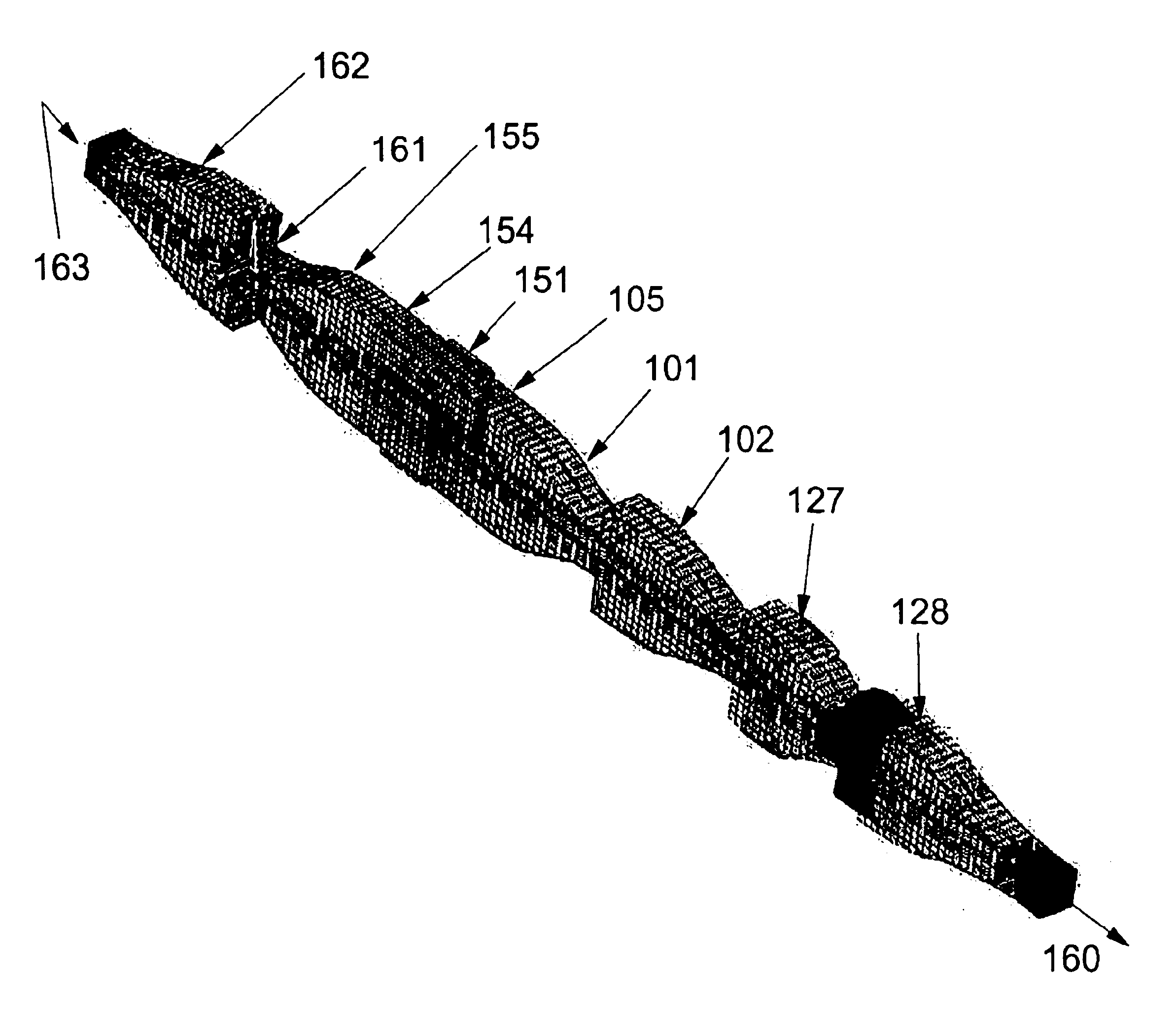
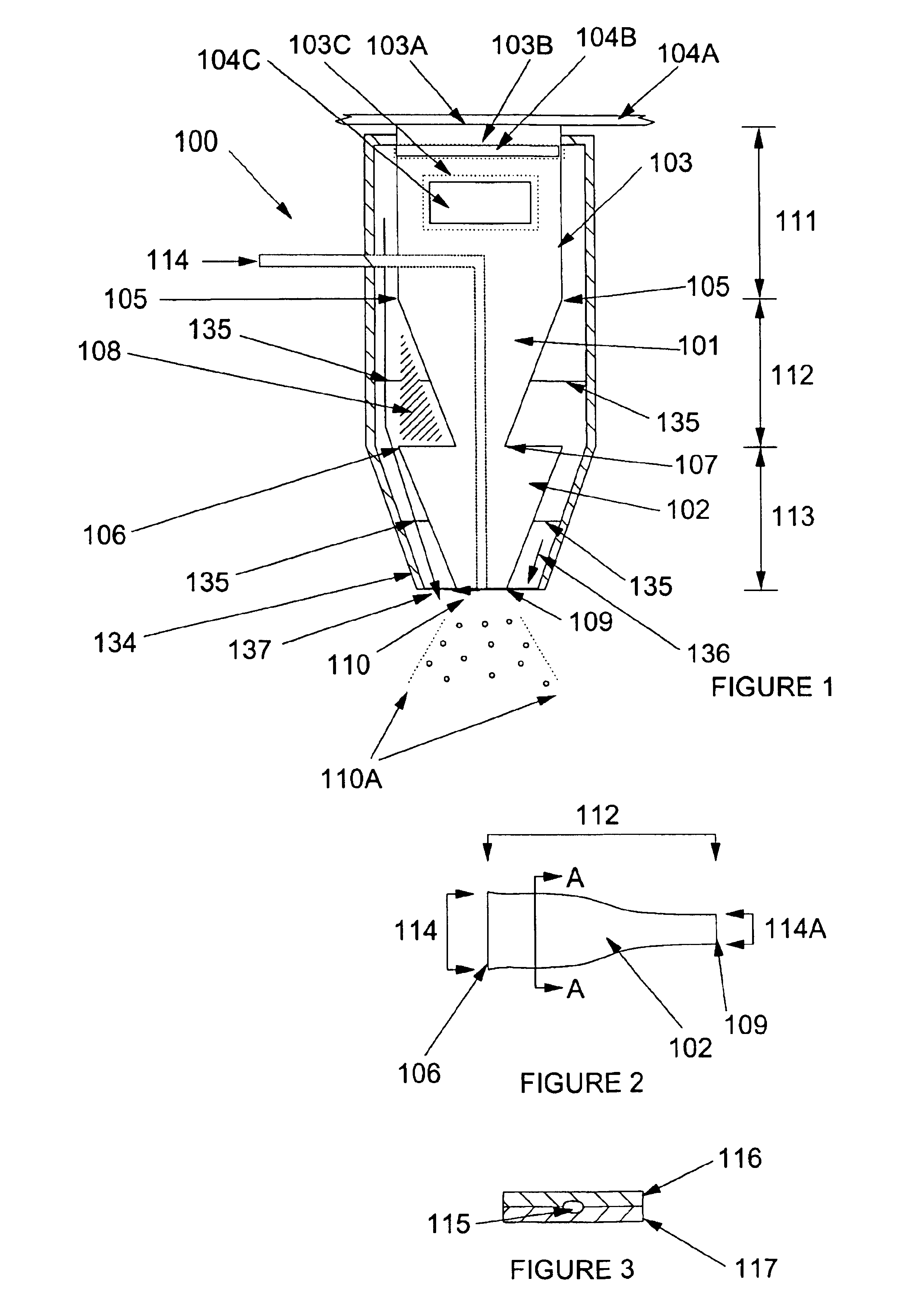
The invention is now discussed with reference to the Figures. FIG. 1 shows a generalized form of an invention nozzle with two horn stages as embodiment 100. A connector base section 103 is a preferred location for transducers in one or more of the locations described above. Section 103 is also a preferred location for connection to a conduit 114 that feeds liquid to a base section opening of conduit 114 for delivery of liquids to the nozzle tip surface 109.

Connector base section 103 can be tapered to provide additional amplitude magnification, as described below. However, as shown in FIG. 1, connector base section 103 is un-tapered and has substantially straight sides with respect to the axis of the nozzle, providing little amplification for the tranducer-supplied vibration. The axis of a nozzle is approximately the center of the liquid conduit leading to the nozzle tip.

Connector base 103 may have a transducer 104A effectively connected with a base 103A or a transducer 104B embedded...


PUM


Abstract

The present invention comprises a nozzle type atomizer with two or more aligned “horn” stages. The definition of a “horn” stage is well known in the prior art as an effectively half wavelength length and a tapering shape with a central conduit. The present invention uses two to five, or more, horn stages integrally attached end to end. The dramatic improvement in amplitude of the vibration at the tip of the nozzle is without precedence in the prior art. The present invention makes application of transducer vibration at greater than 200 kHz possible. The present invention reduces the required applied energy for generating the necessary amplitude at the tip by the discovery of amplitude multiplication with two or more horn stages.

Description

The present invention relates to an handle part of a device used in the production of droplets by application of ultrasonic vibration to the end of one or more nozzles from which a liquid or slurry jet exits.BACKGROUND OF THE INVENTIONProducing droplets of predictable size within a narrow droplet size distribution has been the admirable goal of many prior art attempts. Heat and mass transfer characteristics, as well as other process parameters, change significantly for droplets within the range of diameters typically produced by many prior art devices. Process calculations for modeling such processes with wide droplet size distribution must be subdivided into size groupings and require sophisticated computer-based solutions. Actual operation of processes with wide droplet size distribution generally produces results which are less stable and less predictable than those in which droplet size is effectively narrowed.Capillary wave atomization is done with two general types of devices....

Claims


Application Information

Patent Timeline
Patent Type & Authority Patents(United States)
IPC IPC(8): B05B17/04B05B17/06
CPCB05B17/063B05B17/0623
Inventor TSAI, SHIRLEY CHENG
Owner TSAI SHIRLEY CHENG
Why Eureka
Try Eureka