Dynamic pressure bearing apparatus

a technology bearings, which is applied in the direction of mechanical equipment, sliding contact bearings, rigid support of bearing units, etc., can solve the problems of deteriorating the bearing properties or lifetime abrasion or damage, and an attempt to reduce the longitudinal height of dynamic pressure bearings, etc., to achieve thin dynamic pressure bearings

Inactive Publication Date: 2005-01-04
NIPPON DENSAN CORP
View PDF2 Cites 5 Cited by
  • Summary
  • Abstract
  • Description
  • Claims
  • Application Information

AI Technical Summary

Benefits of technology

Consequently, the present invention is effective for a thin dynamic pressure bearing as it eliminates a rigid plate used f

Problems solved by technology

This has provided an adverse effect on an attempt to reduce the longitudinal height of a dynamic pressure bearing apparatus.
This creates the possibility that the lubrication fluid may leak out from the open gap which is on the opposite end of bearing sleeve 2, subsequently deteriorating the bearing properties or lifetime of the dynamic pressure bearing.
Moreover, as is the case in the apparatus disclosed in Japanese patent application Laid-open (Kokai) No. 2001-289243, in an apparatus having a structure in which a lubrication fluid is filled i

Method used


Image

  • Dynamic pressure bearing apparatus
  • Dynamic pressure bearing apparatus
  • Dynamic pressure bearing apparatus

Examples


Embodiment Construction

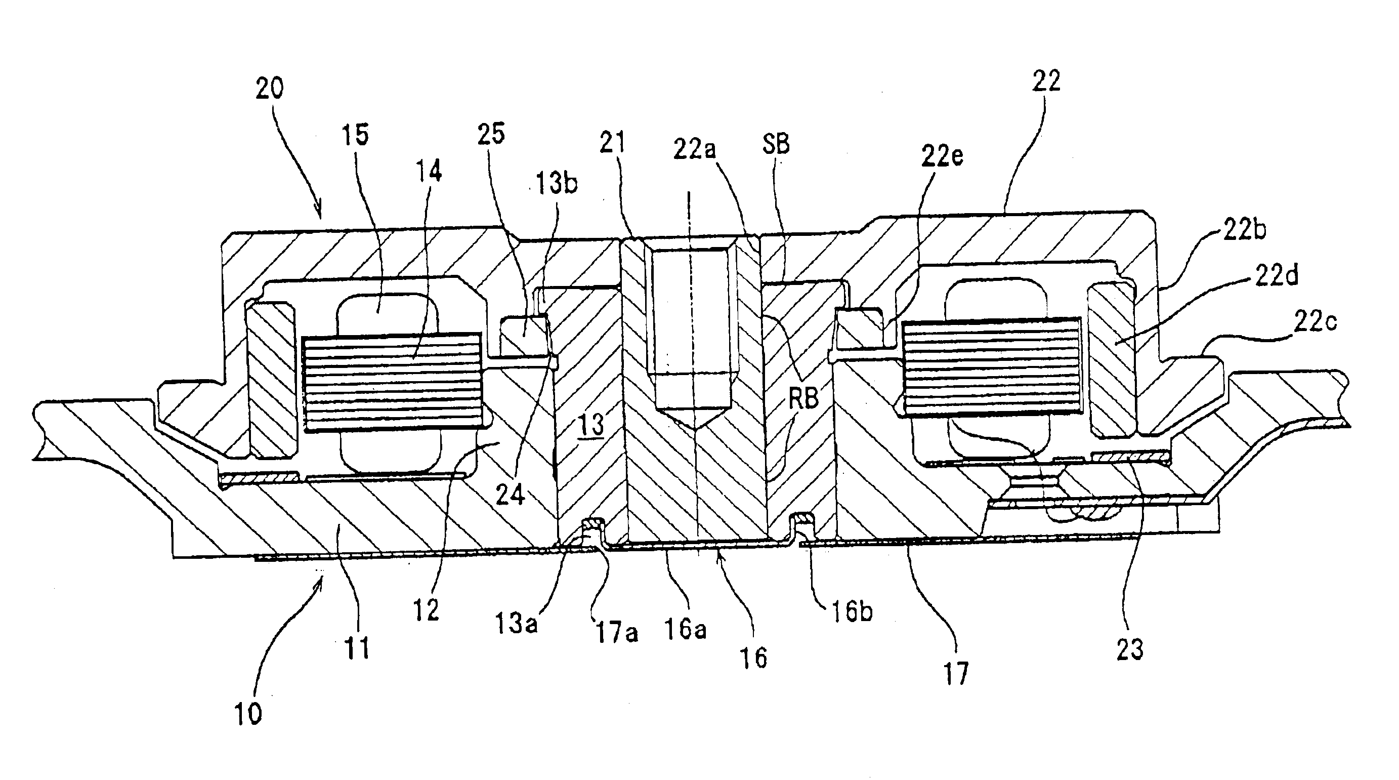
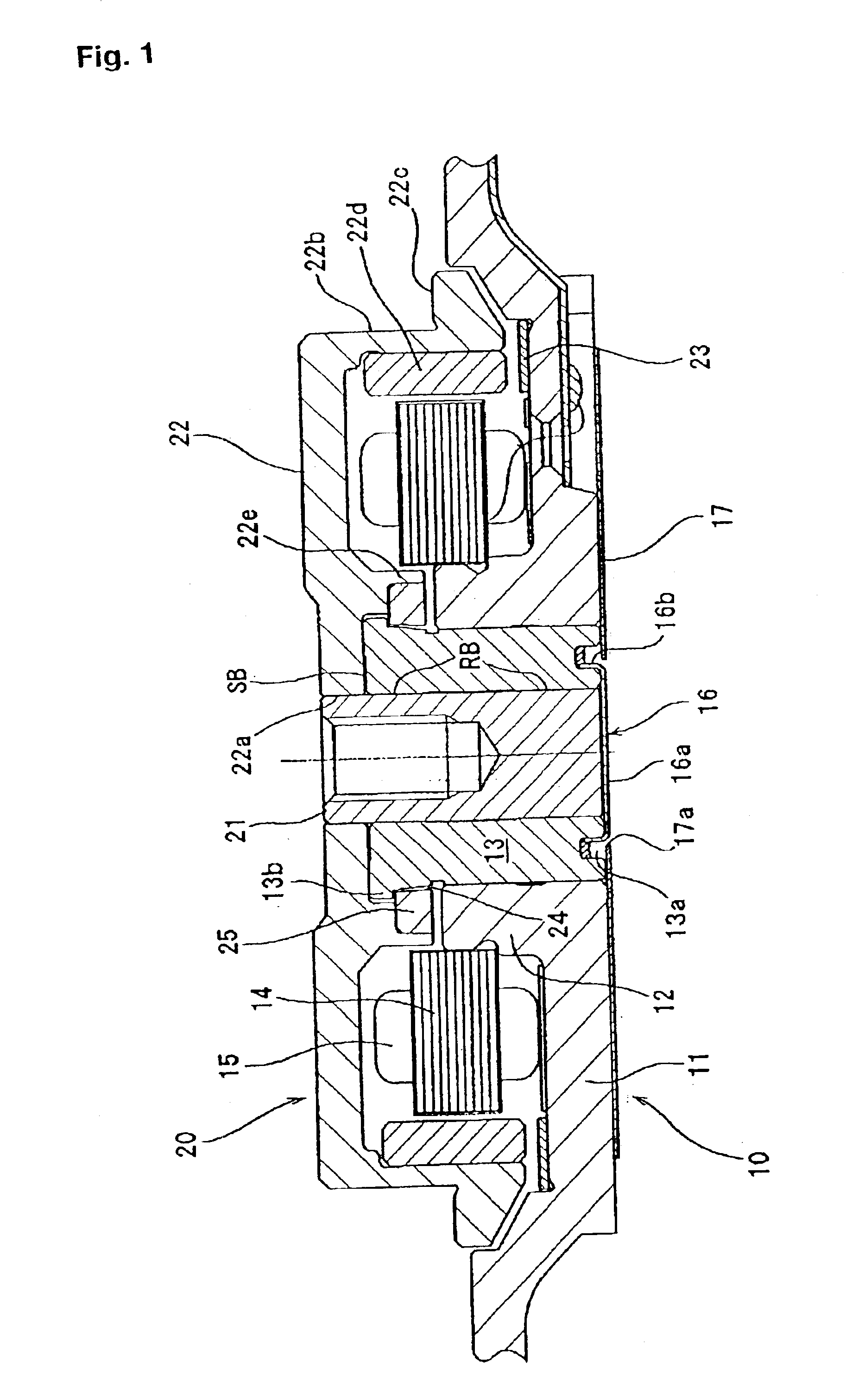
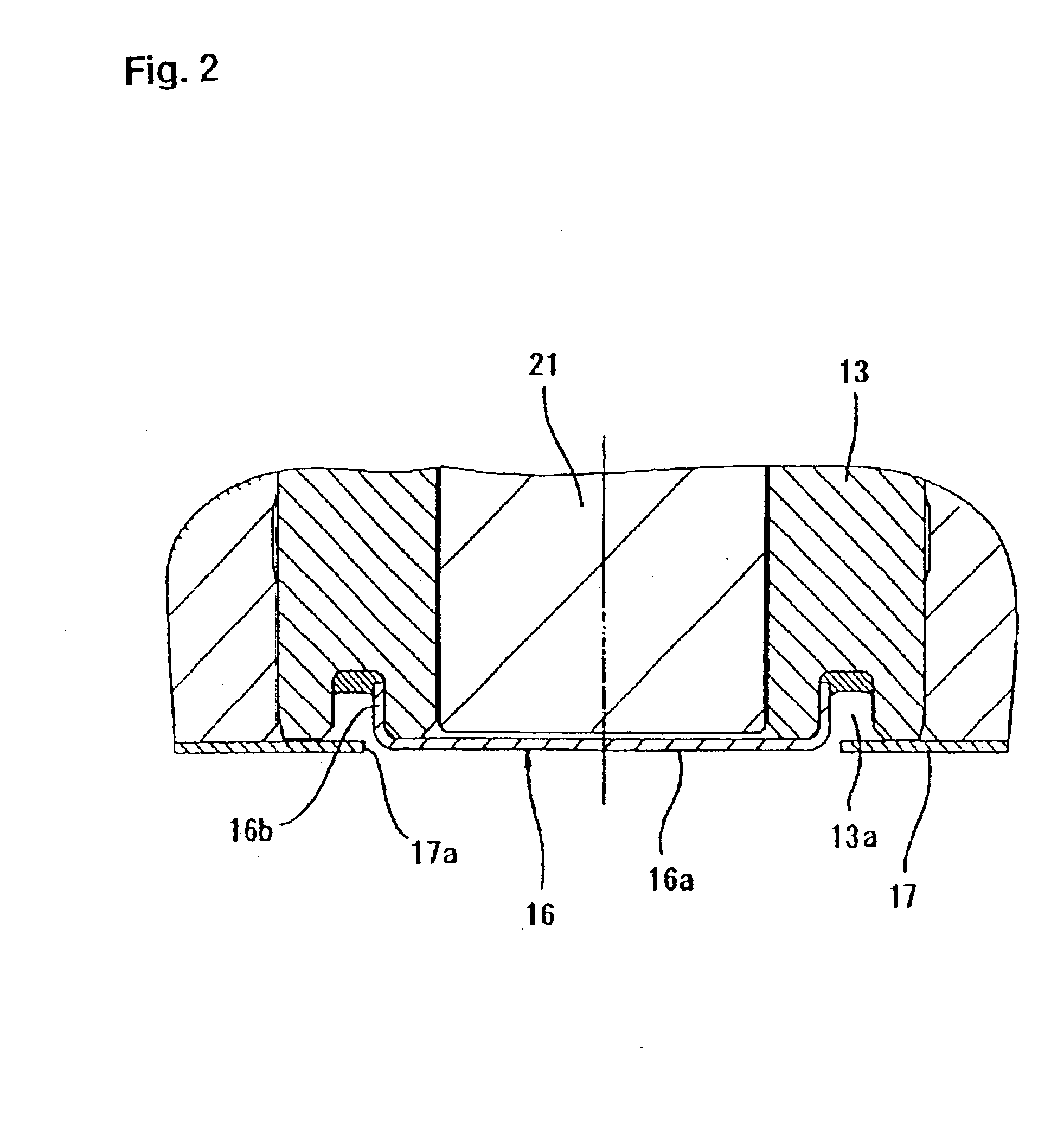
Embodiments of the present invention are described in detail herein. First, an example of applying the dynamic pressure bearing apparatus of the present invention to a hard disk drive is described.

FIG. 1 is an overall view of the rotary shaft type hard disk drive apparatus, which comprises: a stator assembly 10; rotor assembly 20 which is built onto stator assembly 10 from the upper level in the figure. Stator assembly 10 has a securing frame 11, which is screwed onto a fixed base (not illustrated). Securing frame 11 is made of an aluminum type metallic material to help minimize its weight. Bearing sleeve 13, a secured bearing member shaped in a hollow cylinder, is inserted into the inner circumference wall of annular bearing holder 12 to stand on the center of securing frame 11 and is connected to bearing holder 12 by press fitting or shrink fitting. Bearing sleeve 13 is made of copper material such as a Cu—Zn—P alloy to improve machinability, thereby easing drilling of a small hol...


PUM


Abstract

A dynamic pressure bearing apparatus provides a configuration in which the label on which desired data is visibly printed is arranged in a manner that the label does not overlap with a cover plate at least in the area where the label faces the rotary shaft in the shaft direction where the cover plate covers the opening of the bearing sleeve. Deformation of the cover plate that may occur during attachment of the label onto the cover plate is thus prevented. The position of the cover plate is leveled with the position of the label, which makes height reduction of the bearing apparatus possible. Subsequently, even when a relatively thick label is attached onto the frame, the dynamic pressure bearing apparatus can still be made thinner without adversely affecting performance or life thereof.

Description

TECHNICAL FILED OF THE INVENTIONThe present invention relates to a dynamic pressure bearing apparatus having a cover plate attached to the opening of a bearing sleeve that supports the rotary shaft via a lubrication fluid.BACKGROUND OF THE INVENTIONLately, among all types of rotary driving apparatus, the development of a dynamic pressure bearing apparatus that is essentially a rotor that rotates accurately at a high speed has advanced wherein a lubrication fluid generates a dynamic pressure to support a rotary shaft in the dynamic pressure bearing apparatus. For example, in the dynamic pressure bearing motor that is used for a hard disk drive illustrated in FIG. 5, rotary shaft 3 is rotatably inserted into bearing sleeve 2 having a hollow cylindrical shape and is attached to frame 1. A lubrication fluid is injected into a narrow gap between the dynamic pressure bearing sleeve 2 (hereinafter referred to as the “bearing sleeve”) and rotary shaft 3. A dynamic pressure bearing is thus c...

Claims


Application Information

Patent Timeline
IPC IPC(8): F16C33/72H02K5/16F16C17/10F16C33/02F16C33/10F16C35/02F16C41/00H02K5/15H02K7/08
CPCF16C33/723H02K5/1675F16C17/107F16C43/02F16C2370/12
Inventor GOMYO, MASATOSUGINOBU, SHINGOMIURA, KAZUSHI
Owner NIPPON DENSAN CORP
Why Eureka
Try Eureka