Barrier opening and closing mechanism

a technology of opening and closing mechanism and barrier, which is applied in the direction of television system, instruments, camera filters, etc., can solve the problems of increasing the driving load increasing the size of the barrier itself, and complicated structure of the lens barrel, so as to reduce the manufacturing cost of the camera body and simplify the driving mechanism. , the effect of reducing the size of the camera

Inactive Publication Date: 2005-01-04
MINOLTA CO LTD
View PDF7 Cites 9 Cited by
  • Summary
  • Abstract
  • Description
  • Claims
  • Application Information

AI Technical Summary

Benefits of technology

The present invention is made to solve the above-mentioned problem, and an object thereof is to provide a barrier opening and closing mechanism for the inner slide barrier capable of opening and closing the barrier with a simple driving mechanism, reduce the manufacturing cost of the camera body, and attain camera size reduction.
In the above-described structure, since the rotary cam ring rotates on the optical axis, by making the direction of the driving of the driving member by the cam groove parallel to the optical axis, the structure of the barrier opening and closing mechanism can be simplified. Consequently, according to the above-described structure, a driving direction converting mechanism for driving the barrier is not required, so that the structure of the barrier opening and closing mechanism can be simplified.
According to the above-described structure, since the barrier is driven only in a width necessary for opening and closing the taking lens, the stroke of the barrier can be reduced, so that the space for housing the barrier can be reduced.
According to the above-described structure, since the lens is driven only in a width necessary for focusing or zooming and the lens can be made not to be driven while the barrier is being driven, the driving torque can be reduced.
A barrier opening and closing mechanism of the present invention is provided with: a taking lens comprising an incident portion on which light is made incident, a refracting portion refracting incident light substantially at right angles, and a light directing portion directing refracted light to an image sensing device; and a barrier member held so as to be rectilinearly movable in a direction parallel to the light directing portion, and protecting the taking lens by coming out and retracting to and from a front surface of the taking lens in the incident portion.

Problems solved by technology

However, when the collapsible lens barrel is adopted, in the case of the in-barrel barrier, a mechanism for transmitting the driving force from the driving source to the barrier mechanism at the end of the lens barrel is essential, so that it is feared that the lens barrel driving load increases and the structure of the lens barrel is complicated.
In the case of the inner slide barrier, since it is necessary to cover the largest-diameter barrel, the size of the barrier itself increases, so that a space for moving the barrier is required in the camera and large power is necessary for driving the barrier.

Method used


Image

  • Barrier opening and closing mechanism
  • Barrier opening and closing mechanism
  • Barrier opening and closing mechanism

Examples


Embodiment Construction

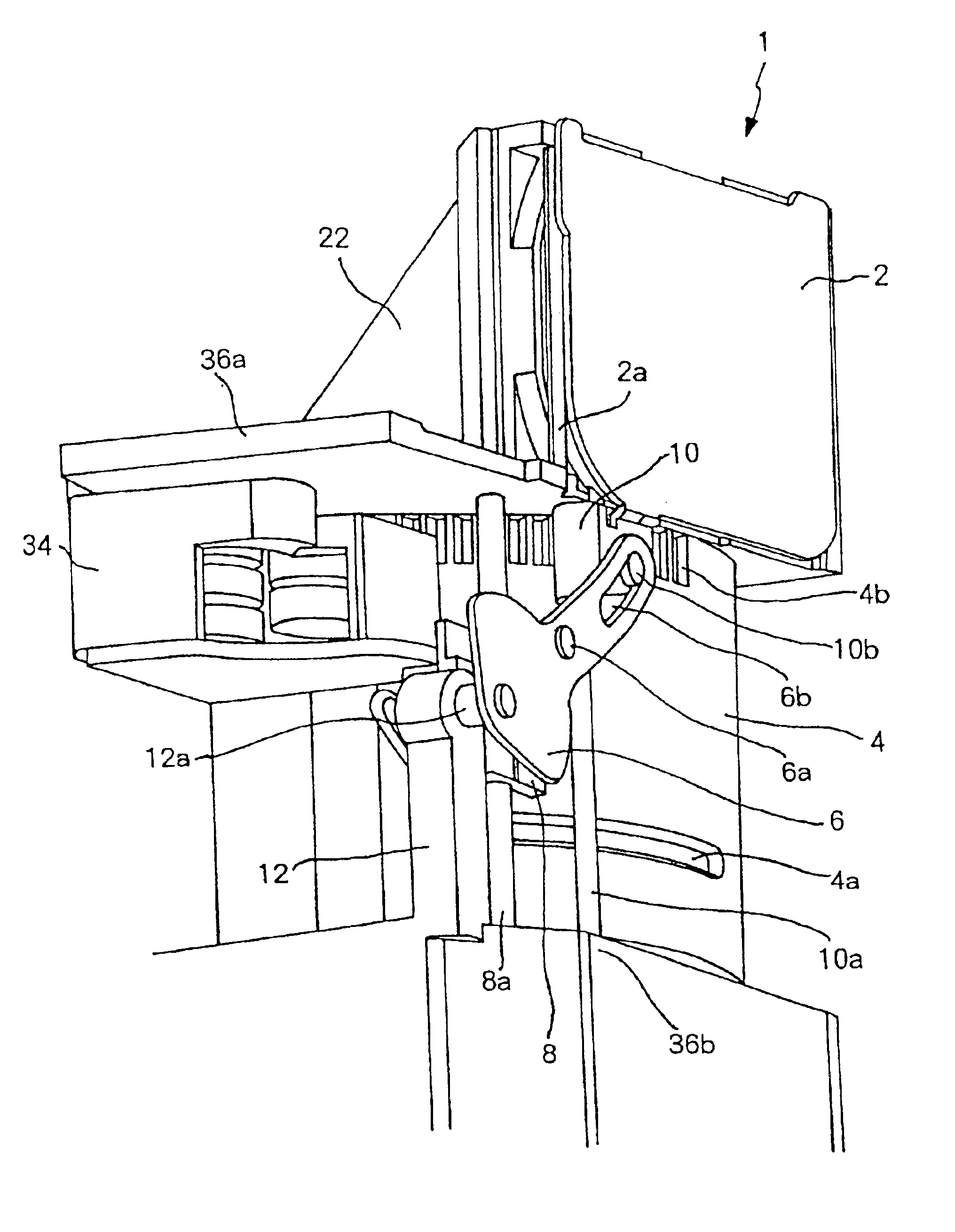
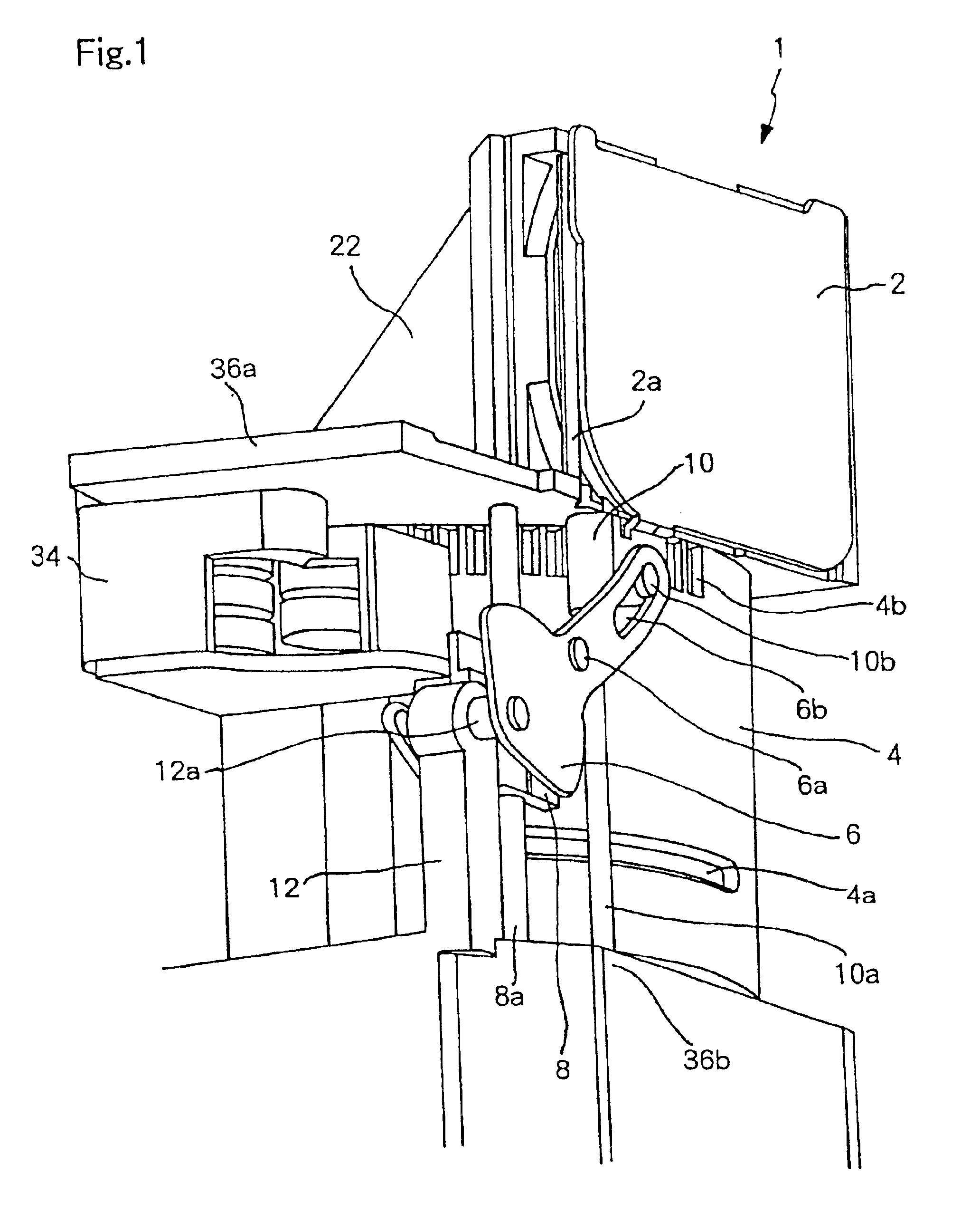
FIG. 1 is an enlarged perspective view of a relevant part of a lens barrel according to an embodiment of the present invention in a condition where the barrier is closed. The lens barrel 1 is disposed in an upright position in a body 32 of a digital camera as shown in the relevant part enlarged side view of FIG. 3. The subject light incident from the taking lens 20 through an opening 32a provided in the body 32 is turned approximately 90 degrees in a vertical direction by a prism 24 disposed in a first lens frame 22, passes through a second lens element 28 (illustrated in FIG. 2) and a zoom lens unit, and is imaged by a non-illustrated CCD disposed in a lower part of the lens barrel 1. The barrier 2 protecting the taking lens is disposed in front of the first lens frame 22 so as to be movable upward and downward. A rotary cam ring 4 is disposed below the first lens frame 22 so as to be concentric with the optical axis of the refracted incident light. The rotary cam ring 4 has a gear...


PUM


Abstract

A barrier opening and closing mechanism includes a refractive optical system having a plurality of lens elements and disposed so as to refract light substantially at right angles; a lens barrel holding the refractive optical system; a rotary cam ring disposed concentrically with the lens barrel, having a first cam groove, and rotating on an optical axis of subject light having been refracted; a lens driving mechanism driving, in a direction of the optical axis, at least one lens element included in the refractive optical system engaged with the first cam groove; and a barrier member protecting a most subject side lens element of the refractive optical system. In the barrier opening and closing mechanism, the rotary cam ring has, in a predetermined angle range on an outer surface thereof, a second cam groove including a region extending obliquely to the optical axis, a driving member is provided that has a cam follower engaged with the second cam groove and is driven in a direction substantially parallel to the optical axis, and the barrier is opened and closed by moving in response to a movement of the driving member in the predetermined angle range.

Description

This application is based on Japanese Paten Application No. Hei 2001-143080 filed in Japan on May 14 2001, the entire content of which is hereby incorporated by reference.FIELD OF THE INVENTIONThe present invention relates to a mechanism for opening and closing a barrier for protecting the taking lens of a camera disposed at an opening through which subject light is incident.DESCRIPTION OF RELATED ARTMany recent cameras incorporate an openable barrier instead of a detachable lens cap. The barrier, which is provided for protecting the taking lens, is fully closed when the camera is not used, and is fully opened when the camera is used. The lens barrier has various types such as a one-bladed type and a two-bladed type.For example, digital cameras using a lens barrel comprising at least two barrels coupled so as to be collapsible (hereinafter, referred to as a collapsible lens barrel) are known, and as the barrier opening and closing mechanism used in the lens barrel of the digital cam...

Claims


Application Information

Patent Timeline
Patent Type & Authority Patents(United States)
IPC IPC(8): G03B17/02G03B11/04G03B17/04G03B17/17H04N5/225H04N101/00
CPCG03B17/02
Inventor SHINTANI, DAI
Owner MINOLTA CO LTD
Why Eureka
Try Eureka