Substrate treating apparatus

Active Publication Date: 2005-01-04
SCREEN HLDG CO LTD
View PDF3 Cites 30 Cited by
  • Summary
  • Abstract
  • Description
  • Claims
  • Application Information

AI Technical Summary

Benefits of technology

Preferably, the main transport mechanism is arranged, when transferring substrates to and from one of the inlet substrate rests and one of the outlet substrate rests, with one of the holding arms holding a substrate, and the other holding arm unloaded, to drive the one of the holding arms and transfer the substrate to the one of the outlet substrate rests, and thereafter to drive one of the holding arms, both now unloaded, and receive a different substrate from the one of the inlet substrate rests. After one of the holding arms places the substrate on one of the outlet substrate rests, the two holding arms of the main transport mechanism are empty. The following advantage results from having the two holding arms of the main transport mechanism temporarily empty. When, for example, trouble has occurred with a certain treating module in a treating block (or controlled unit), the main transport mechanism with the two holding arms empty may be moved toward this treating module to transport substrates to a location of temporary storage. If the other, empty holding arm first receives a substrate and the one holding arm thereafter passes the substrate to the substrate rest, a substrate is constantly present on either one of the holding arms. It is thus difficult to transport substrates for temporary storage in time of trouble as noted above.
Preferably, the main transport mechanism has at least two holding arms for holding the substrates, and the main transport mechanism is arranged, when transferring substrates to and from one of the inlet substrate rests and one of the outlet substrate rests, with one of the holding arms holding a substrate, and the other holding arm unloaded, to drive the one of the holding arms and transfer the substrate to the one of the outlet substrate rests, thereafter to determine whether an abnormality has occurred with a destination forward or backward with respect to a direction of transport through one of the treating blocks or controlled units in which the main transport mechanism is disposed, and when an abnormality is confirmed, to transport the substrates only in a direction free from the abnormality. With this construction, after transferring the substrate from one of the holding arms to one of the outlet substrate rests, it is determined whether an abnormality has occurred with a destination forward or backward with respect to a direction of transport through the treating block or controlled unit in which the main transport mechanism is disposed. When an abnormality has occurred, substrates are transported only in a direction opposite to the forward or backward direction encumbered by the abnormality. Thus, substrates may be transported smoothly in the direction free from the abnormality to realize an efficient substrate transport.
It is also preferred that the treating modules include heat-treating modules having heating plates for heating the substrates and cooling plates for cooling the substrates, and the main transport mechanism is arranged to drive one of the at least two holding arms in unloaded state to receive a different substrate from one of the inlet substrate rests, to fulfill a condition that, in every transport cycle, the same one of the at least two holding arms receives substrates heated by the heating plates. This construction can assign the task of receiving substrates heated by the heating plates exclusively to one of the holding arms. Thus, the

Problems solved by technology

Consequently, the conventional substrate treating apparatus canno

Method used


Image

  • Substrate treating apparatus
  • Substrate treating apparatus
  • Substrate treating apparatus

Examples


Example

A preferred embodiment of this invention will be described in detail hereinafter with reference to the drawings.

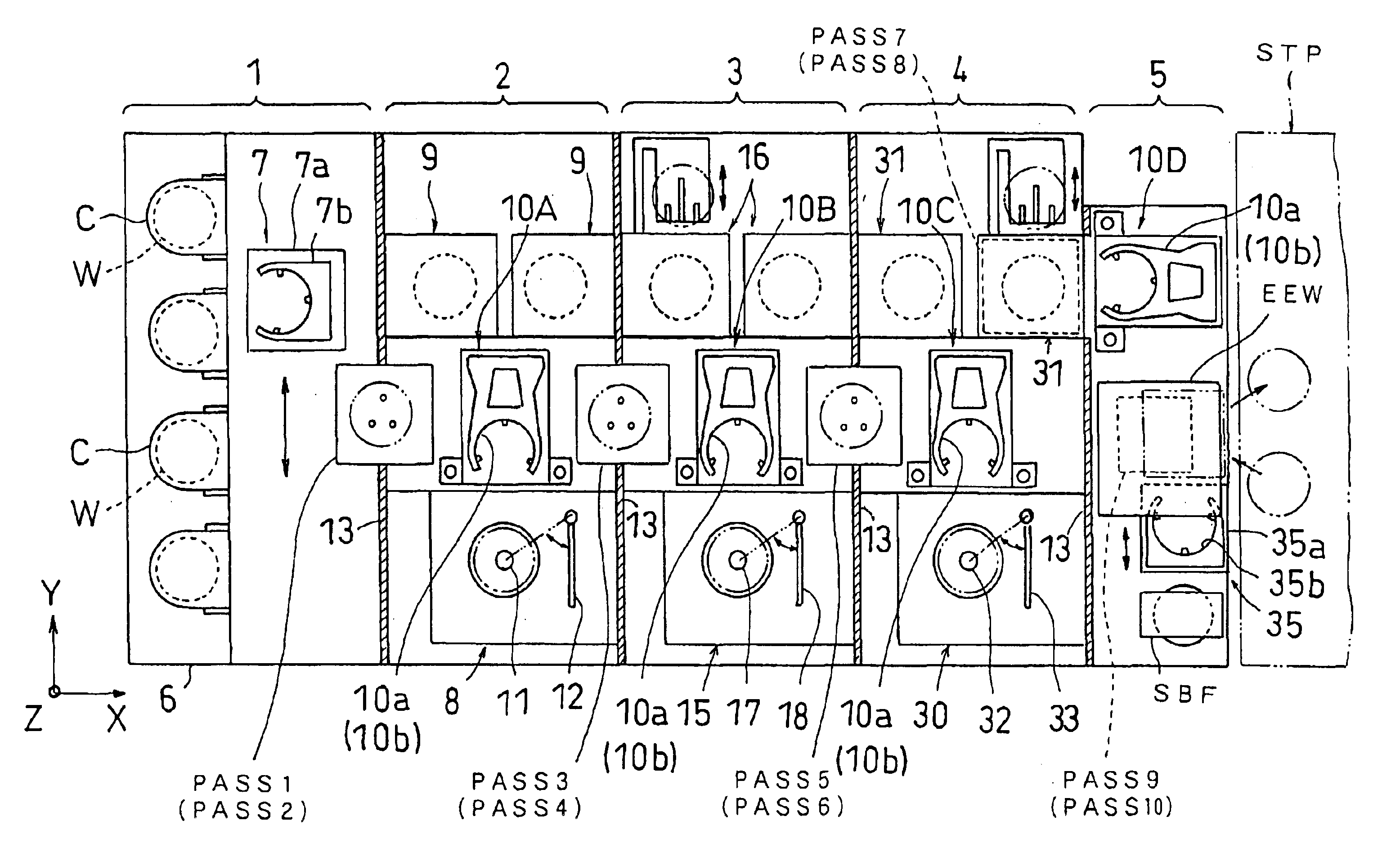
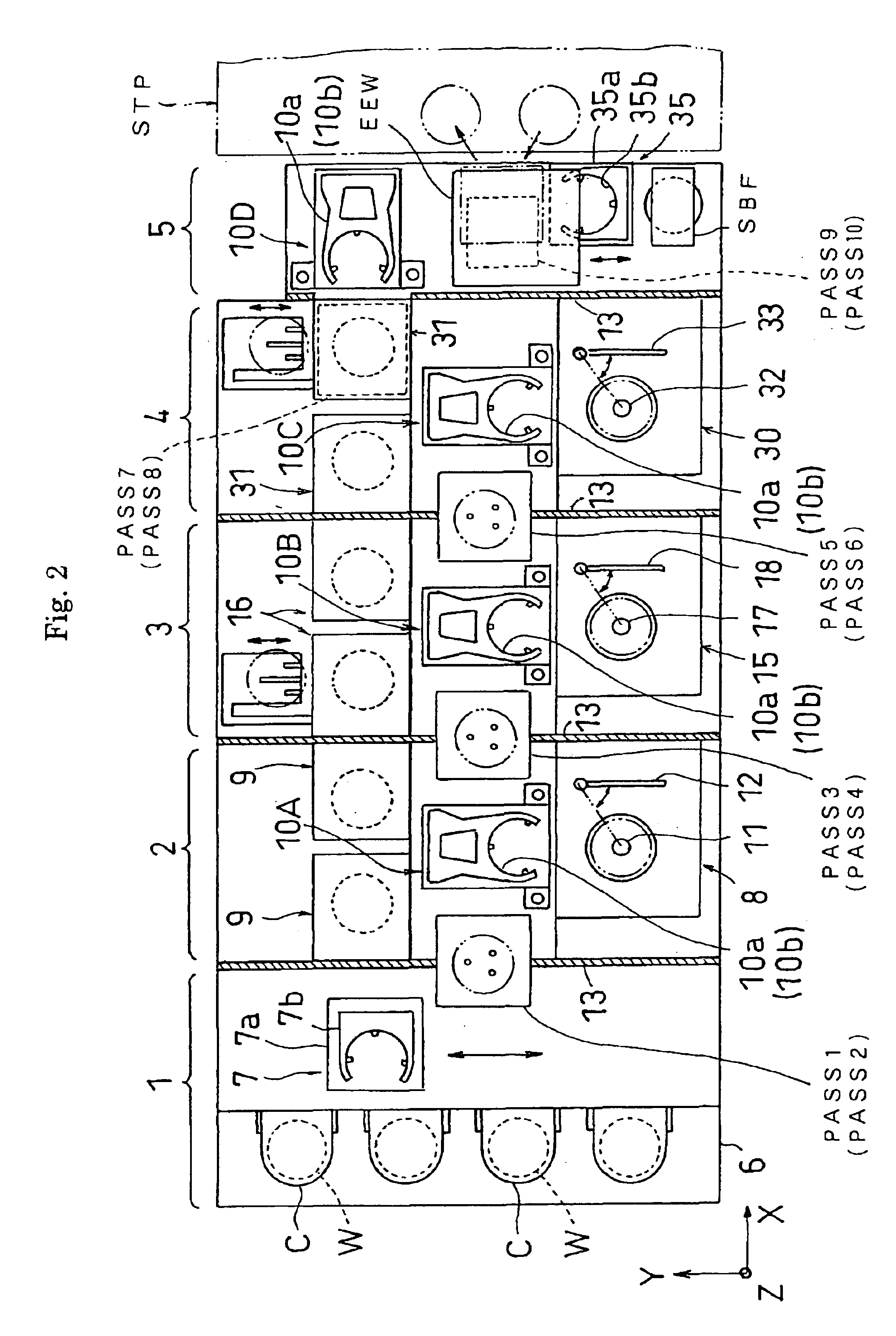
FIG. 2 is a plan view showing an outline of a substrate treating apparatus according to this invention. FIG. 3 is a front view of the apparatus. FIG. 4 is a front view of heat-treating modules.

This substrate treating apparatus is constructed to perform chemical treatment for forming antireflection film and photoresist film on semiconductor wafers (hereinafter called simply “substrates or wafers”), and developing exposed substrates. The substrates handled by the substrate treating apparatus according to this invention are, of course, not limited to semiconductor wafers, but include various substrates such as glass substrates for liquid crystal displays. The chemical treatment is not limited to formation of photoresist film or the like or development, but includes various other chemical treatments.

FIG. 2 refers. The substrate treating apparatus in this embodiment, broadly, i...


PUM


Abstract

A substrate treating apparatus has an antireflection film forming block, a resist film forming block and a developing block arranged in juxtaposition, each of these blocks including treating modules and a single main transport mechanism. The main transport mechanism transports substrates within each block, and transfers the substrates between the blocks through inlet substrate rests and outlet substrate rests provided as separate components. This construction realizes improved throughput of the substrate treating apparatus.

Description

BACKGROUND OF THE INVENTION(1) Field of the InventionThis invention relates to a substrate treating apparatus for performing a series of treatments of substrates such as semiconductor wafers, glass substrates for liquid crystal displays, glass substrates for photomasks, and substrates for optical disks (hereinafter called simply “substrates”).(2) Description of the Related ArtConventionally, such a substrate treating apparatus is used, for example, in a photolithographic process for forming photoresist film on substrates, exposing the substrates having the photoresist film formed thereon, and developing the exposed substrates.This apparatus will be described with reference to a plan view shown in FIG. 1. This substrate treating apparatus includes an indexer 103 having a cassette table 101 for receiving a plurality of cassettes C each for containing a plurality of (e.g. 25) wafers W to be treated, or wafers W having been treated in treating modules 104 described hereinafter, and a tr...

Claims


Application Information

Patent Timeline
IPC IPC(8): H01L21/00B65G49/07H01L21/027H01L21/677H01L21/68
CPCH01L21/67173H01L21/67184H01L21/67178Y10S414/135H01L21/68
Inventor KOYAMA, YASUFUMIKAMEI, KENJIKITAMOTO, TORUHASHINOKI, KENJIYAMAMOTO, SATOSHIDAININ, TOSHIAKI
Owner SCREEN HLDG CO LTD
Why Eureka
Try Eureka