Vehicle window glass holder

a technology for window glass and holder, which is applied in the direction of wing accessories, couplings, rod connections, etc., can solve the problems of difficult to remove the rivet, easy breakage of the window glass, and difficulty in removing the holder from the window glass, so as to facilitate the fixing of the window glass and the easy extraction of the shaft

Inactive Publication Date: 2005-01-04
NIPPON SHEET GLASS CO LTD +1
View PDF3 Cites 20 Cited by
  • Summary
  • Abstract
  • Description
  • Claims
  • Application Information

AI Technical Summary

Benefits of technology

It is an object of the present invention to provide a holder, comprising a shaft and a holding member, and capable of easily fixing a window glass to the holding member only by rotating the shaft, and capable of easily extracting the shaft from the holding member by reversely rotating the shaft, the shaft and the holding member being able to be reused.
It is another object of the invention to provide a holder capable of preventing the breakage of a window glass when a load is applied thereto.
The holder can further comprise a mechanism for preventing the reverse rotation of the shaft when the shaft is rotated.

Problems solved by technology

However, such conventional attaching structure, where the tube-like member is cut by the blade of the shaft-like member to be radially opened, results in the difficulty of removing the rivet.
In addition, with regard to the rivet, there is a problem of easy breakage of the window glass, which is caused by the abutment of the inner peripheral surface edge of the attaching hole to the rivet when a load is applied to the window glass.
Such holder is difficult to be detached away from the window glass because of its strong adhesive strength thereto.
Therefore, there is a problem in that the holder may not be reused and the window glass may not only be reused itself but also be recycled as cullet.

Method used


Image

  • Vehicle window glass holder
  • Vehicle window glass holder
  • Vehicle window glass holder

Examples


first embodiment

(First Embodiment)

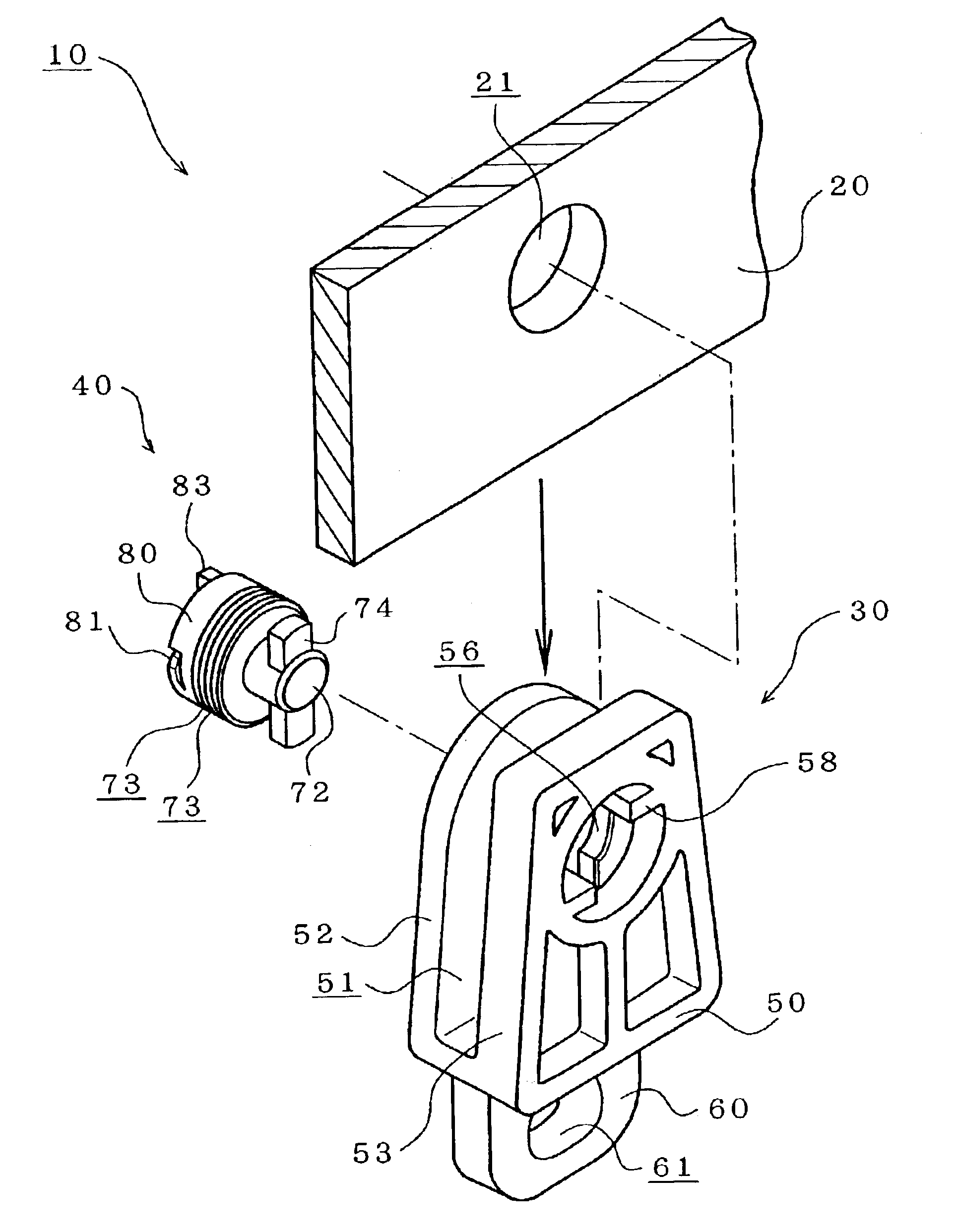
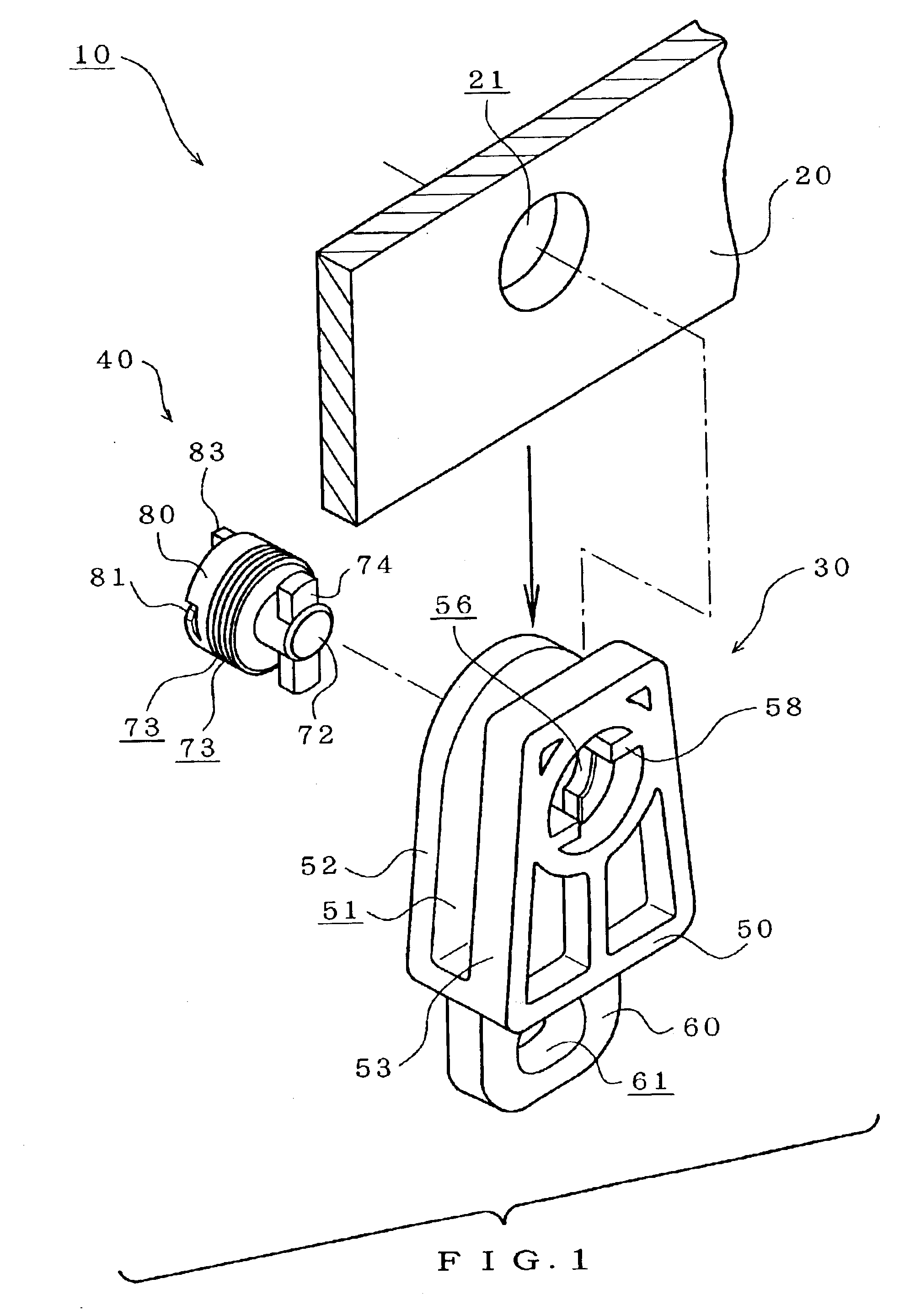
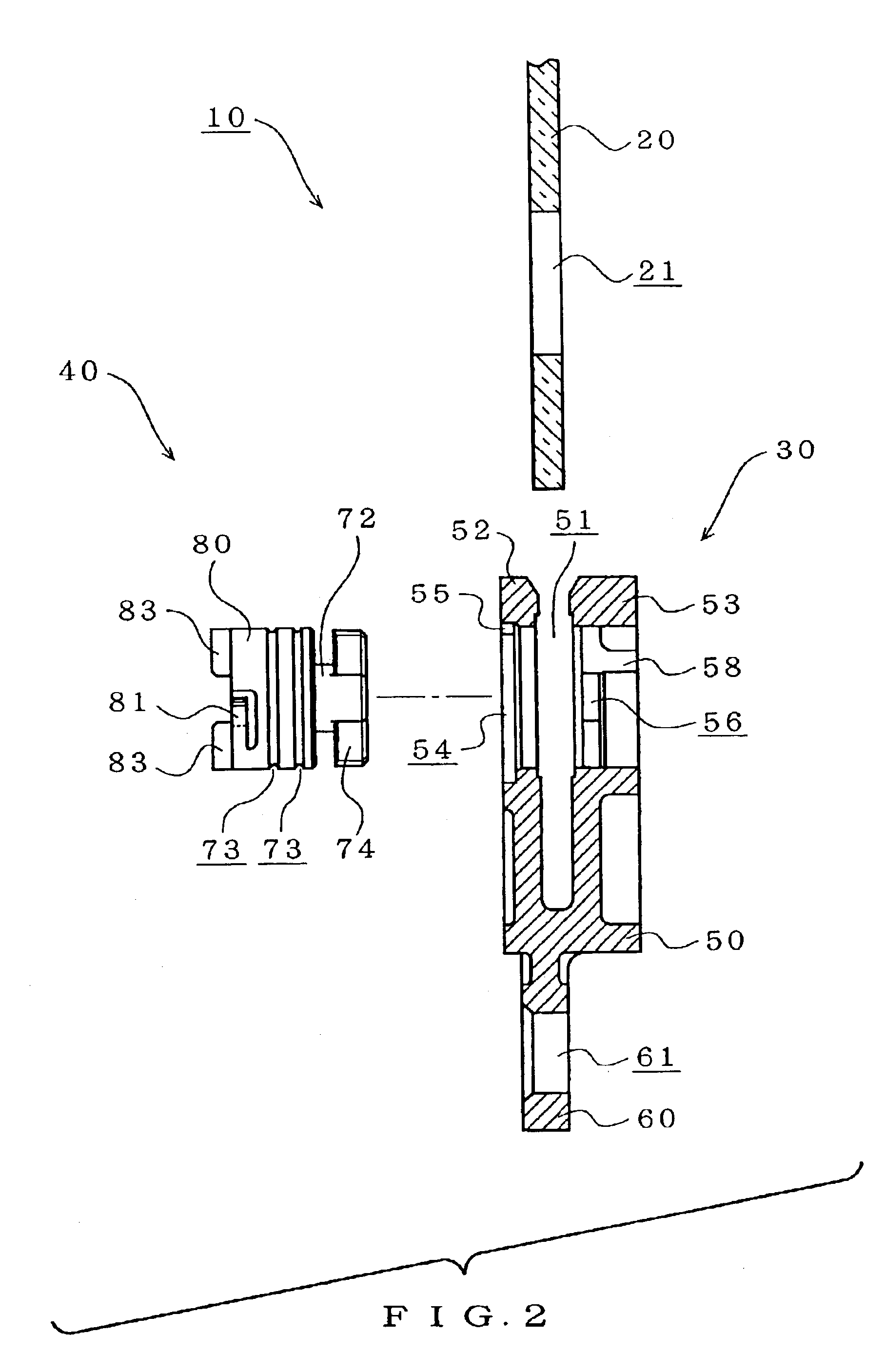
Now, description will be made of a holder according to a first embodiment of the present invention with reference to FIGS. 1 to 16. As shown in FIGS. 1 and 2, a holder 10 comprises a holding member 30 and a shaft 40. As shown in FIGS. 1 to 3, the holding member 30 includes portion 51 into which a window glass 20 is inserted (referred to as a window glass inserting portion hereinafter). As shown in FIGS. 3 to 7, the holding member 30 also includes a main body 50, and a connecting portion 60. Such holding member 30 is integrally formed by using a thermoplastic resin, for example, nylon, having proper rigidity.

As shown in FIGS. 1 and 2, the shaft 40 is designed to fix the window glass 20 in the window glass inserting portion 51 of the holding member 30. As shown in FIGS. 8 to 11, the shaft 40 includes two projecting pieces 74 provided on its tip, a support portion 72 for supporting the projecting pieces, and a main body 80. Such shaft 40 is integrally formed by using ...

second embodiment

(Second Embodiment)

Next, description will be made of a holder according to a second embodiment of the present invention. The first embodiment is directed to the reverse-rotation preventing mechanism based on the locking of the elastic piece 81 provided at the end of the shaft 40 with the tapered step 55 provided on the inner peripheral surface of the shaft inserting hole 54 of the holding member main body.

The second embodiment is directed to a reverse-rotation preventing mechanism based on the locking of an elastic piece protruded from each of projecting pieces provided at the tip of the shaft with a recess provided at the peripheral part of the shaft inserting hole 56 of the holding member main body.

FIG. 18 is an exploded perspective view illustrating the holder of the second embodiment, and FIG. 19 a right side view of the holding member. An elastic piece 75 is integrally formed on a projecting piece 74 provided at the tip of the shaft 40, the elastic piece being opposed to the sh...

third embodiment

(Third Embodiment)

Next, description will be made of a third embodiment of the present invention by referring to FIGS. 20 and 21. According to the embodiment, as shown in FIGS. 20 and 21, a buffer member 90 is fixed to the bottom surface of the window glass inserting portion 51 of the holding member 30. As shown in FIG. 20, the buffer member 90 is sheet-shaped. A horizontal width of the buffer member 90 is set so as to be larger than the width of the window glass inserting portion 51. A total length of the buffer member 90 is set so as to be equal to or lower than the length of the portion 51. A felt sheet material, for example, can be used for the buffer member 90. The material of the buffer member 90 is not limited to such felt, and rubber or sponge may be used.

When the buffer member 90 is inserted into the window glass inserting portion 51, as shown in FIG. 21, the buffer member 90 is bent in a U-shape along the bottom surface of the portion 51. Accordingly, even when a force is a...


PUM


Abstract

A vehicle window glass holder is disclosed, which is capable of easily fixing a window glass only by rotating a shaft, and easily extracting the shaft by reversely rotating the shaft to allow reuse. The holder comprises a holding member and a shaft. The shaft includes projecting pieces provided on its tip, a support portion for supporting the projecting pieces, and a main body connected to the support portion. The holding member includes a pair of opposing pieces, and each of the opposing pieces has an shaft inserting hole. The shaft is inserted into the holes of the holding member. By rotating the shaft, the shaft is engaged with the holding member, and thus the shaft is prevented from being extracted from the holding member.

Description

TECHNICAL FIELDThe present invention relates to a vehicle window glass holder and, more particularly, to an attaching structure of a window glass.BACKGROUND ARTThe holder is designed to hold, for example the window glass of an automobile, connected to a window regulator mechanism incorporated in a door, and is elevated / lowered while holding the window glass. One of such vehicle window glass holders available in the conventional art has been known in Japanese Utility Model Publication No. 54-38648 titled in “ELEVATING / LOWERING DEVICE ATTACHING STRUCTURE FOR AUTOMOBILE WINDOW GLASS”.The conventional attaching structure disclosed in the above Publication includes an attaching hole formed in a window glass. The window glass is fixed through a rivet to the attaching hole. The rivet is composed of tube-like and shaft-like members. The shaft-like member is pulled to cut the tube-like member by its blade, and the wide-open part of the tube-like member is radially opened.However, such conven...

Claims


Application Information

Patent Timeline
Patent Type & Authority Patents(United States)
IPC IPC(8): E05F11/38B60J1/17
CPCE05F11/385E05F2011/387E05Y2900/55Y10T403/7007Y10T403/7005Y10T403/75Y10T403/4611Y10T403/535Y10T403/4614F16B2005/0671
Inventor KANATANI, YASUKAZUMAGARA, KATSUMIOGAWA, ATSUSHI
Owner NIPPON SHEET GLASS CO LTD
Why Eureka
Try Eureka