Gas turbine engine

a gas turbine engine and turbine engine technology, applied in the direction of machines/engines, wind motors with perpendicular air flow, climate sustainability, etc., can solve the problems of increasing pressure loss, accelerating and decelerating the flow rate on the upper face of the airfoil, etc., to reduce the flow rate on the upper face of the blade main body, reduce weight, and improve the performance of the gas turbine engin

Inactive Publication Date: 2005-01-04
HONDA MOTOR CO LTD
View PDF11 Cites 40 Cited by
  • Summary
  • Abstract
  • Description
  • Claims
  • Application Information

AI Technical Summary

Benefits of technology

When the thickness of the turbine airfoil of the gas turbine engine is decreased in order to reduce the weight, the stagger angle required increases, the flow rate of combustion gas on the upper face of the front half of a blade main body accelerates and decelerates rapidly and, in particular, in the case of a high load blade having a high rotor inlet relative Mach number, the flow rate reaches a critical Mach number, thus generating a shock wave and thereby causing a large pressure loss and degrading the performance of the gas turbine engine. However, in accordance with the present invention, since the cross section in the axial direction along the connecting section of the inner peripheral wall or the outer peripheral wall of the gas turbine engine where the wall is connected to the turbine airfoil has a concave part on the front edge side and a convex part on the rear edge side via a point of inflection, the concave part having a negative curvature relative to a direction of flow of gas, and the convex part having a positive curvature, the flow rate on the upper face of the blade main body can be reduced in the concave part on the front edge side, thus suppressing generation of a shock wave, and the flow rate can be increased in the convex part on the rear edge side following the concave part, thus smoothly changing the flow rate on the upper face of the blade main body and thereby minimizing the pressure loss. In this way, the thickness of the blade main body can be reduced while maintaining the performance of the gas turbine engine, thereby contributing to a reduction in weight.
This effect can be exhibited even more strongly by making the height of the convex part at most 10% of the length, in the radial direction, of the gas passage, positioning the point of inflection between the concave part and the convex part so as to be forward of the central position of the chord, making the absolute value of the negative curvature of the concave part smaller than the absolute value of the positive curvature of the convex part, arranging for the minimum negative pressure point that is the closest to the front edge of the conventional turbine airfoil to be present within the range of the concave part, and positioning the front end of the concave part so as to be to the rear of the front edge.

Problems solved by technology

1), but since the curvature of the front half on the upper face of the airfoil increases with an increase in the stagger angle γ, the flow rate on the upper face of the airfoil accelerates and decelerates rapidly and, in particular, in the case of a high load blade having a high rotor inlet relative Mach number, a shock wave is generated beyond a critical Mach number, and as a result there is the problem that the pressure loss increases.

Method used


Image

  • Gas turbine engine
  • Gas turbine engine
  • Gas turbine engine

Examples


Embodiment Construction

A mode for carrying out the present invention is explained below by reference to an embodiment of the present invention illustrated in attached drawings.

FIG. 1 and FIG. 2 show one embodiment of the present invention.

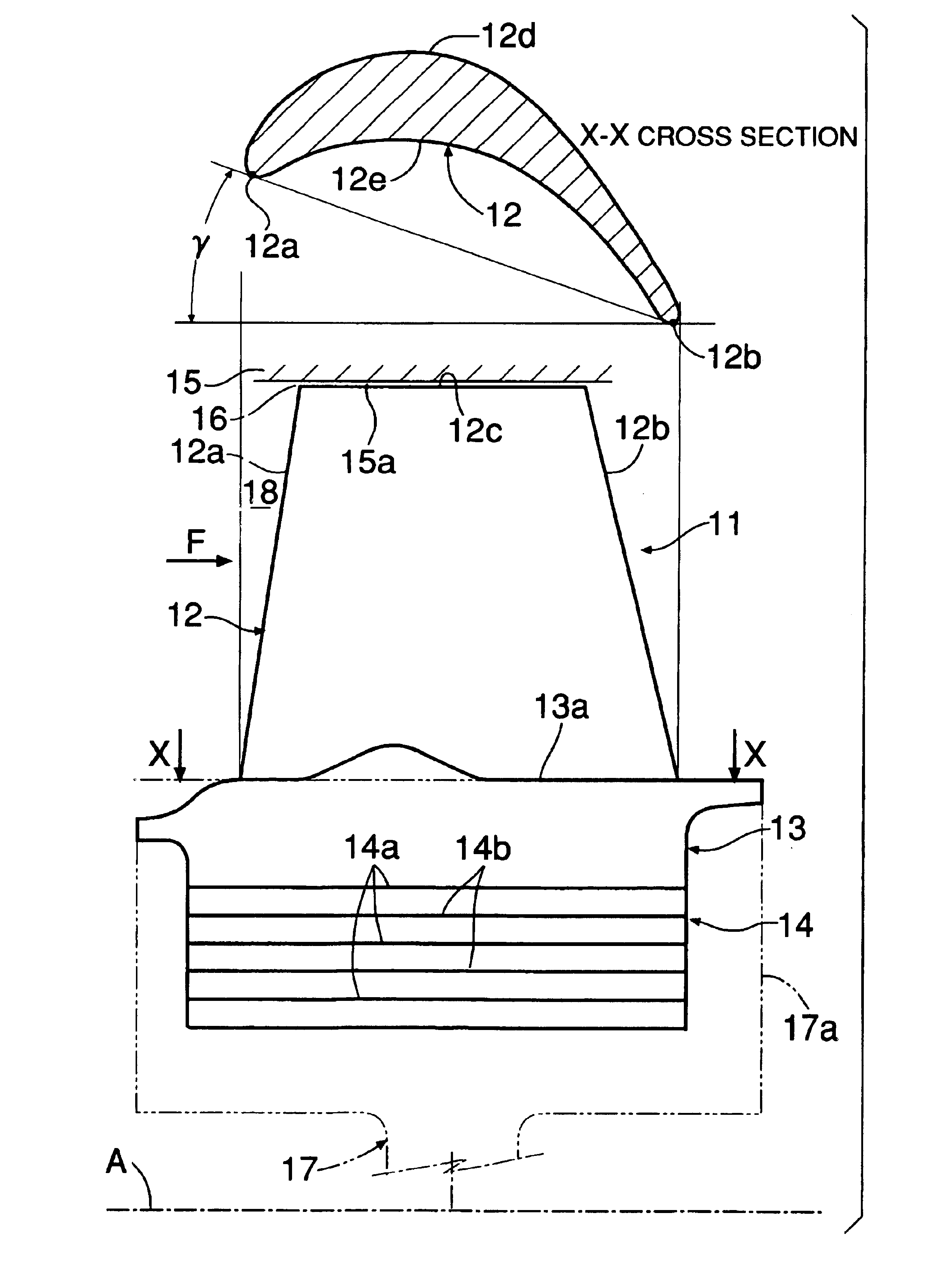
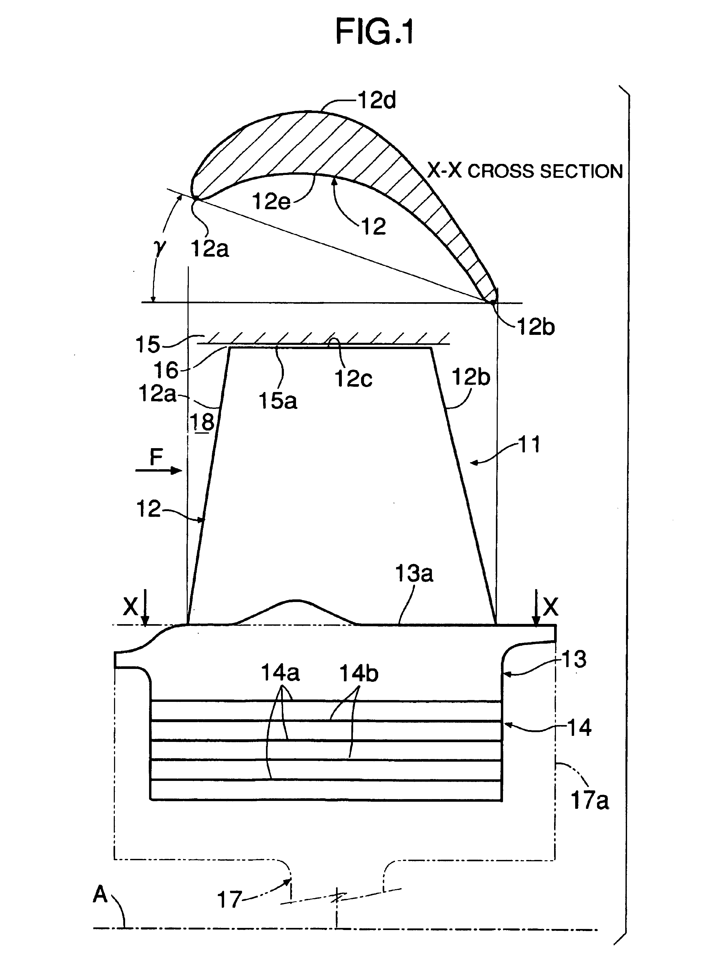
FIG. 1 shows a turbine blade 11 of an axial-flow gas turbine engine, and the turbine blade 11 is formed from a blade main body 12 positioned outward in the radial direction, a blade end wall 13 positioned inward in the radial direction relative to the blade main body 12, and a blade mounting part 14 positioned inward in the radial direction relative to the blade end wall 13. The blade shape of the root part (a part adjoining the blade end wall 13) of the blade main body 12 shown as the cross section X—X in FIG. 1 comprises a front edge 12a, a rear edge 12b, an upper face 12d, and a lower face 12e, and a straight line joining the front edge 12a and the rear edge 12b has a comparatively large stagger angle γ relative to the direction of the axis A of the gas turbine engine...


PUM


Abstract

A gas turbine engine has, in a cross section in the axial direction of an annular inner peripheral wall connected to a blade main body of a turbine blade, a concave part and a convex part on the front edge side and the rear edge side. The concave part has a negative curvature and is concave toward the axis, and the convex part has a positive curvature and is convex away from the axis. The flow rate on the upper face of the blade main body can be reduced in the concave part on the front edge side, thus suppressing generation of a shock wave, and the flow rate can be increased in the convex part on the rear edge side following the concave part, thus smoothly changing the flow rate on the upper face of the blade main body and thereby minimizing the pressure loss. In this way, the thickness of the blade main body can be reduced while ensuring the performance of the gas turbine engine, thereby contributing to a reduction in weight.

Description

FIELD OF THE INVENTIONThe present invention relates to a gas turbine engine in which turbine airfoils are disposed in a radial direction in an annular gas passage defined by an inner peripheral wall and an outer peripheral wall.BACKGROUND ARTJapanese Patent Application Laid-open No. 11-241601 discloses an axial-flow gas turbine engine comprising stator vanes and rotor blades, wherein a cross section in the axial direction of an inner peripheral wall of a casing to which the stator vanes and the rotor blades are connected has a concave part that recedes radially inward relative to a straight line joining the front edge of the root of the stator vane on the front side and the rear edge of the root of the rotor blade on the rear side.Furthermore, U.S. Pat. No. 5,466,123 discloses an arrangement in which a cross section orthogonal to the axial direction of an inner peripheral wall of a casing supporting stator vanes of a gas turbine engine has sinusoidally alternating concave parts and ...

Claims


Application Information

Patent Timeline
Patent Type & Authority Patents(United States)
IPC IPC(8): F01D5/14
CPCF01D5/141F01D5/145F05D2240/302F05D2250/711Y02T50/673F05D2250/712Y02T50/671Y02T50/60
Inventor KAWARADA, SATOSHISONODA, TOYOTAKA
Owner HONDA MOTOR CO LTD
Why Eureka
Try Eureka