Marine gas cylinder apparatus

a gas cylinder and apparatus technology, applied in marine propulsion, shock absorption devices, vessel construction, etc., can solve the problems of heavy load, excessive hydraulic pressure of communication chambers, and inability to make the propulsion unit in a tilt-lock state at an optional position, so as to reduce the switching force of the switching valve apparatus and move the propulsion unit easily up.

Inactive Publication Date: 2005-01-04
HITACHI ASTEMO LTD
View PDF5 Cites 1 Cited by
  • Summary
  • Abstract
  • Description
  • Claims
  • Application Information

AI Technical Summary

Benefits of technology

The present invention relates to a marine gas cylinder apparatus that allows for easy movement and positioning of a propulsion unit while also reducing the force required to switch a valve. The apparatus includes a cylinder block connected to either a hull or a propulsion unit, with a piston rod connected between the cylinder block and the propulsion unit. The cylinder block has separate oil chambers for the piston rod and the propulsion unit, with a gas chamber formed integrally within the cylinder block. A switching valve apparatus is provided in the cylinder block, which can switch between the oil chambers and the gas chamber. The valve apparatus includes check valves that open and close all the communication passages simultaneously, allowing for easy movement and positioning of the propulsion unit. A temperature compensating relief valve is also included to relieve oil from the communication chamber to the gas chamber. The technical effect of this invention is to provide a more efficient and effective gas cylinder apparatus for marine applications.

Problems solved by technology

In the prior art in the patent publication 1, since a gas chamber is provided in an inner portion of the piston rod side oil chamber, it is impossible to lock movement of the piston even by shutting off the communication between the piston rod side oil chamber and the piston side oil chamber on the basis of a closing operation of the switching valve apparatus, so that it is impossible to make the propulsion unit in a tilt-lock state at an optional position.
As described above, since the communication chamber of the switching valve apparatus forms the sealed space, the hydraulic pressure of the communication chamber becomes excessively high at a time when the working fluid in the communication chamber is expanded due to the abnormal temperature increase.
Therefore, a heavy load is required for opening the check valve, and there is a risk that the switching valve apparatus becomes broken.

Method used


Image

  • Marine gas cylinder apparatus
  • Marine gas cylinder apparatus
  • Marine gas cylinder apparatus

Examples


Embodiment Construction

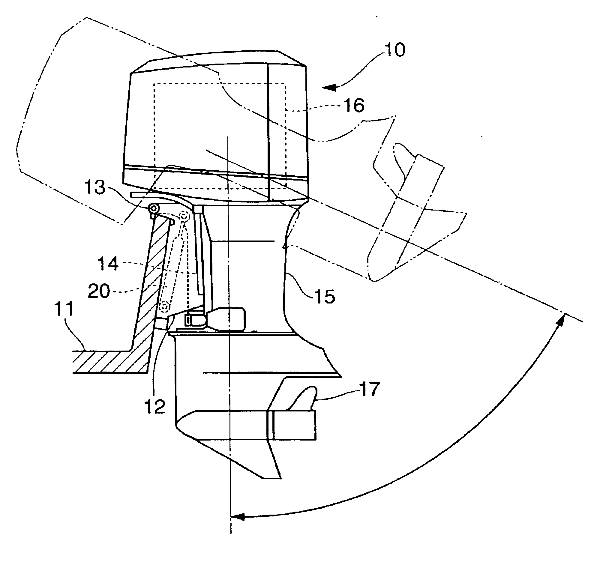
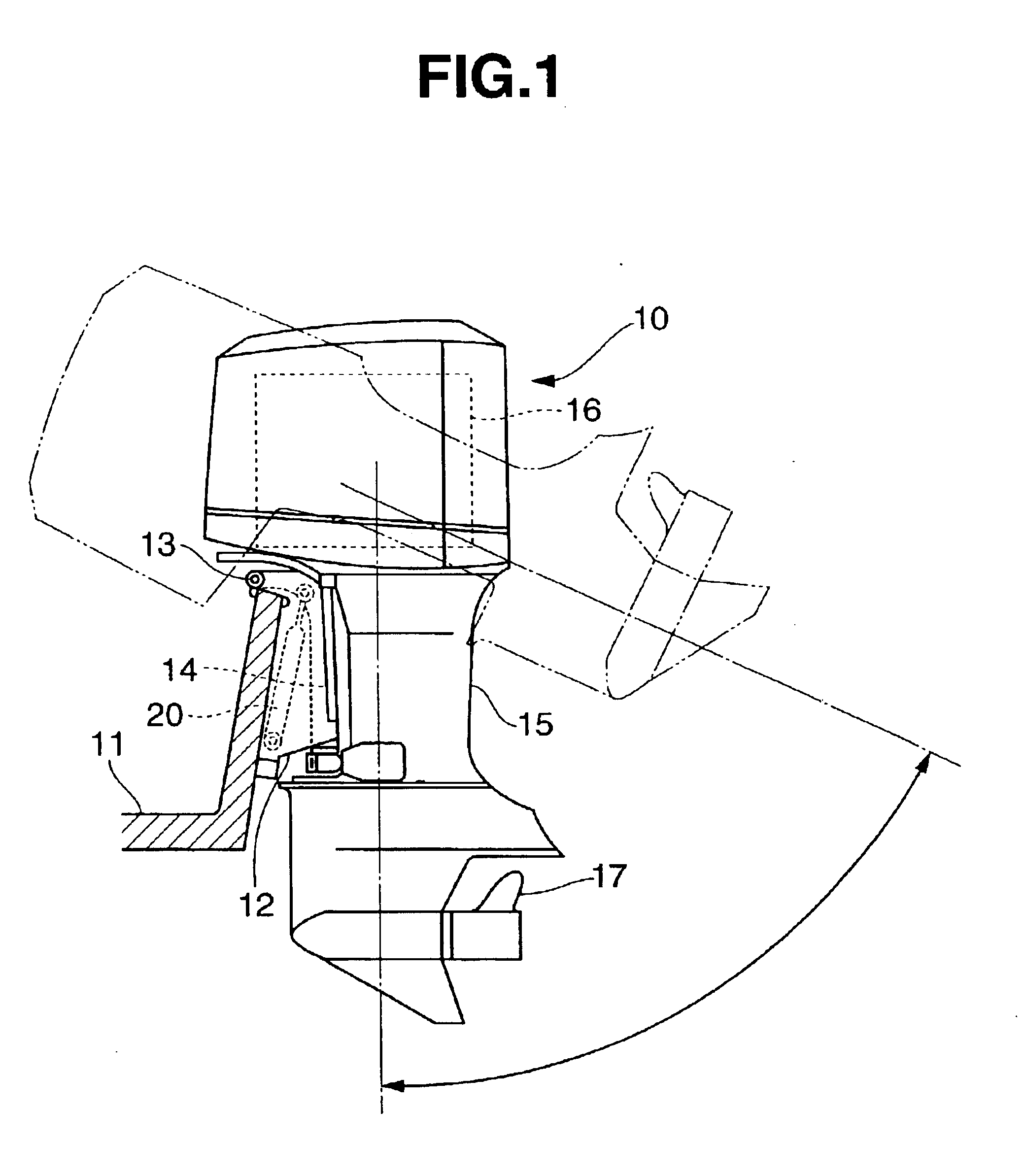
A marine propulsion unit, for example an outboard motor, an inboard-outdrive motor, or other type is shown in FIG. 1 as an embodiment 10. Clamp bracket 12 is fixed to a hull 11. A swivel bracket 14 is pivoted to the clamp bracket 12 via a tilt shaft 13 so as to be capable of tilting around an approximately horizontal axis. A propulsion unit 15 is pivoted to the swivel bracket 14 via a rudder turning axis (not shown) so as to be capable of rotating around an approximately vertical axis. The propulsion unit 15 drives a propeller 17 by an engine unit 16.

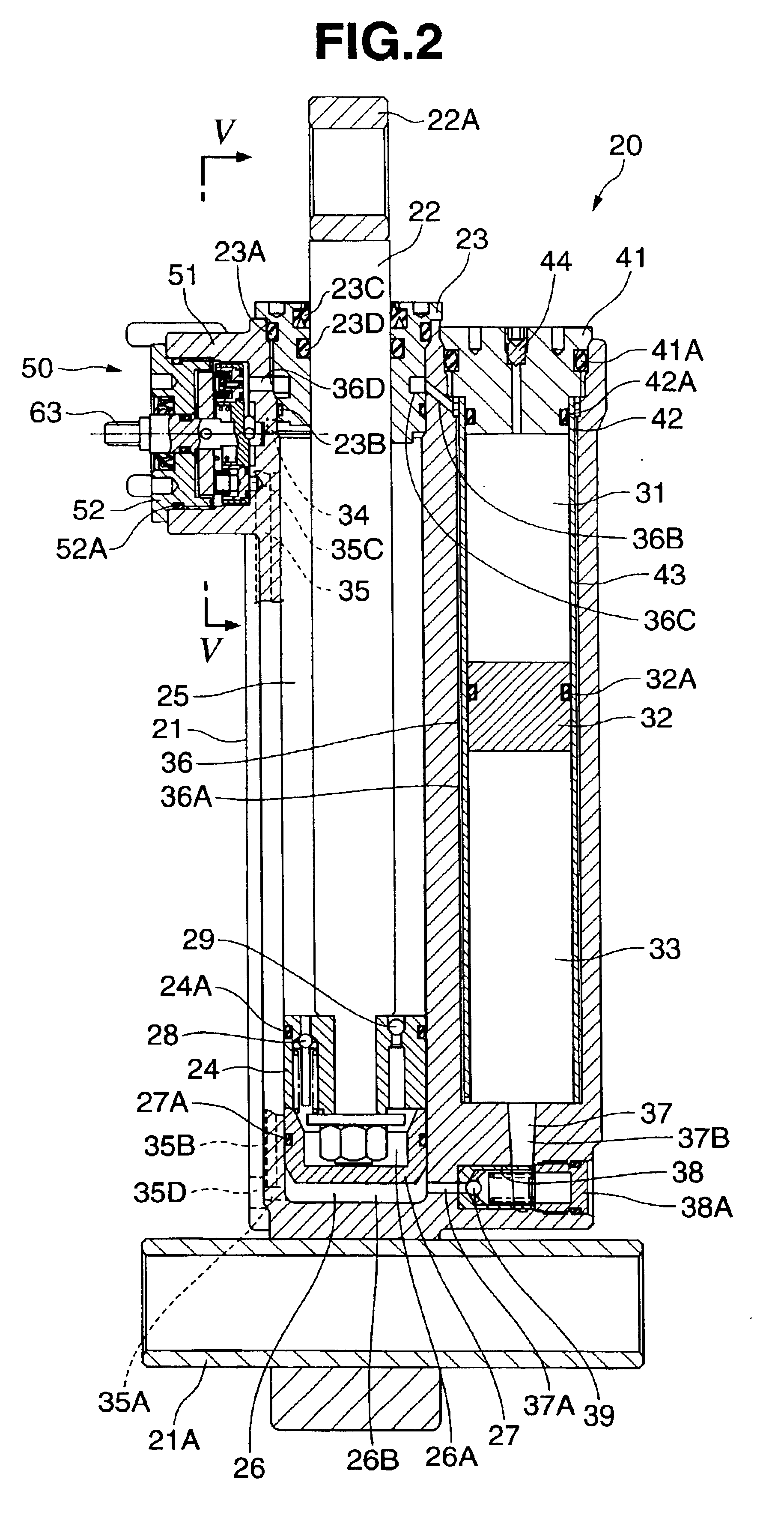
The marine propulsion unit 10 is provided with a gas cylinder apparatus 20 between the clamp bracket 12 and the swivel bracket 14. The gas cylinder apparatus 20 has a cylinder block 21 casted of an aluminum alloy or the like, and a piston rod 22, as shown in FIGS. 2 to 4. The piston rod 22 is inserted in a liquid tight manner from a rod guide 23 which is screwed in a liquid tight manner with the cylinder block 21 via O-rings 23A and 23B...


PUM


Abstract

In a marine gas cylinder apparatus provided with a switching valve apparatus capable of switching a communication state among a piston rod side oil chamber, a piston side oil chamber and a gas chamber, a relief passage communicating a communication chamber of the switching valve apparatus with the gas chamber is provided. A temperature compensating relief valve relieving an oil in the communication chamber to the gas chamber is provided in the relief passage.

Description

BACKGROUND OF THE INVENTION1. Field of the InventionThe present invention relates to a marine gas cylinder apparatus.2. Description of the Related ArtConventionally, as described in Japanese Patent Application Publication No. 7-81682 (patent publication 1), a marine gas cylinder apparatus includes a structure in which a cylinder block is connected to one of either a hull or a propulsion unit. A piston rod inserted into the cylinder block from a rod guide provided in the cylinder block is connected to the corresponding hull or propulsion unit. A piston rod side oil chamber in a side which receives the piston rod and a piston side oil chamber in a side which does not receive the piston rod are provided within the cylinder block. High pressure gas is charged into a portion above a working fluid in the piston rod side oil chamber, and a switching valve apparatus capable of switching a communication state among the piston rod side oil chamber and the piston side oil chamber is provided i...

Claims


Application Information

Patent Timeline
Patent Type & Authority Patents(United States)
IPC IPC(8): B63H20/00B63H20/10F16F9/46F16F9/56F16F9/44B63H20/08
CPCB63H20/10F16F9/56F16F9/462
Inventor SEKIKAWA, SHINSUKE
Owner HITACHI ASTEMO LTD
Why Eureka
Try Eureka