Temperature detection unit in a high-frequency heating and cooking apparatus

Inactive Publication Date: 2005-01-04
PANASONIC CORP
View PDF10 Cites 37 Cited by
  • Summary
  • Abstract
  • Description
  • Claims
  • Application Information

AI Technical Summary

Benefits of technology

In order to solve the above-described conventional problems, the present invention provides a heating and cooking ap

Problems solved by technology

Thus, the infrared rays may not possibly reach the infrared ray sensor 7 so that the temperature of the foo

Method used


Image

  • Temperature detection unit in a high-frequency heating and cooking apparatus
  • Temperature detection unit in a high-frequency heating and cooking apparatus
  • Temperature detection unit in a high-frequency heating and cooking apparatus

Examples


first embodiment

(First Embodiment)

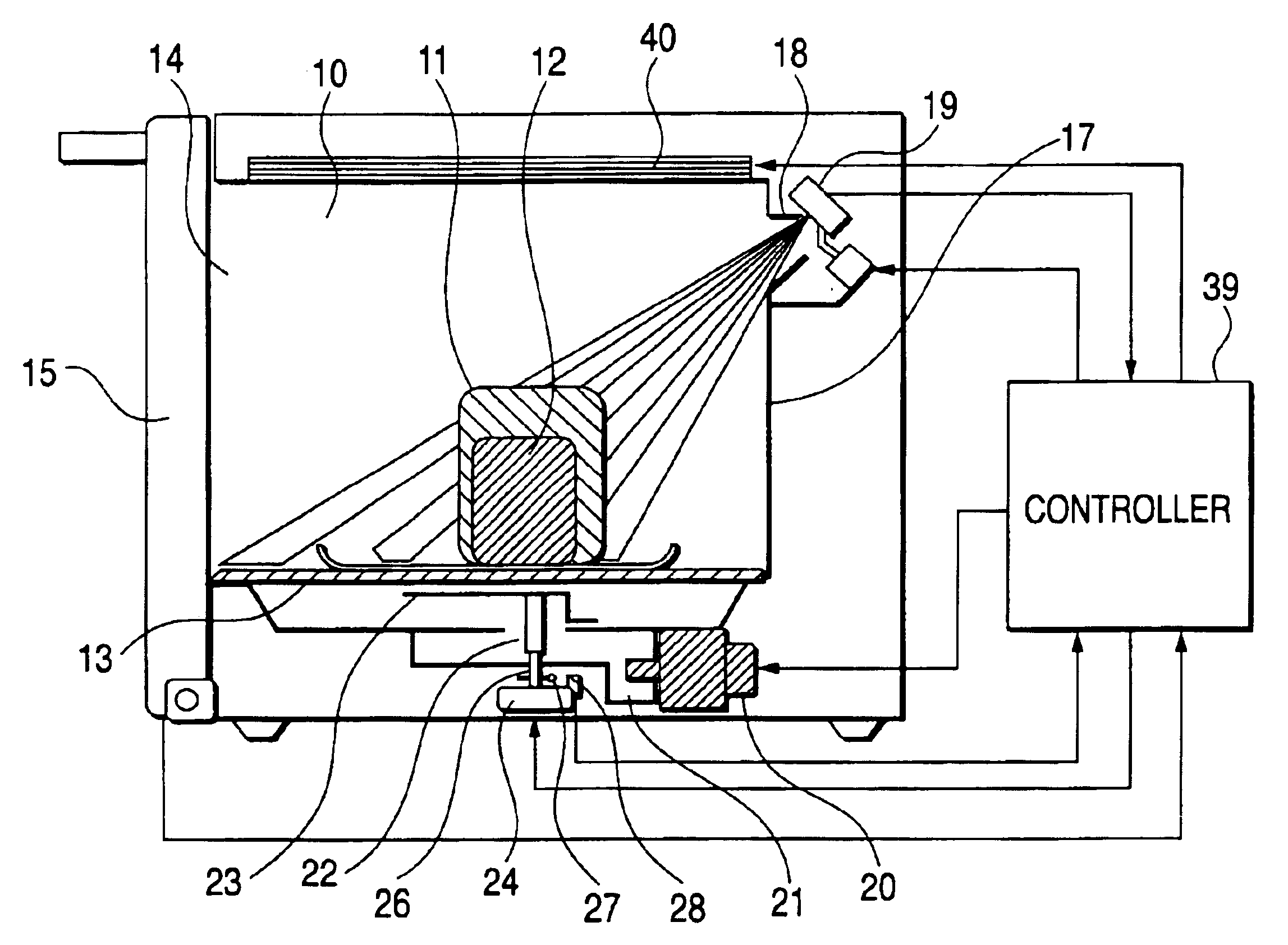
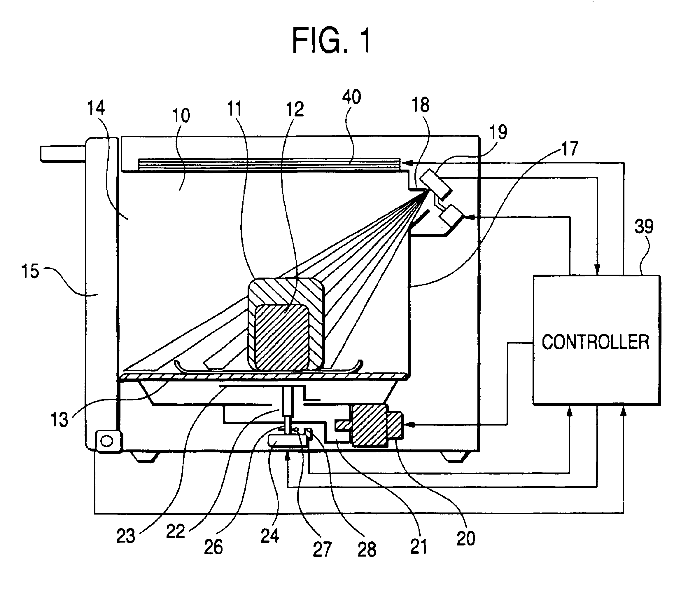
FIG. 1 is a sectional view of a heating and cooking apparatus according to a first embodiment of the present invention.

In FIG. 1, reference numeral 10 designates a heating chamber for accommodating foods 11 and 12. The foods 11 and 12 are mounted on a sealing means 13 substantially the same as the bottom surface of the heating chamber 10. For the sealing means 13, a material having electric wave penetrability such as glass, ceramics or a resin is used. In an opening part 14 for taking in and out the foods of the heating chamber 10, a freely opened and closed door 15 is provided.

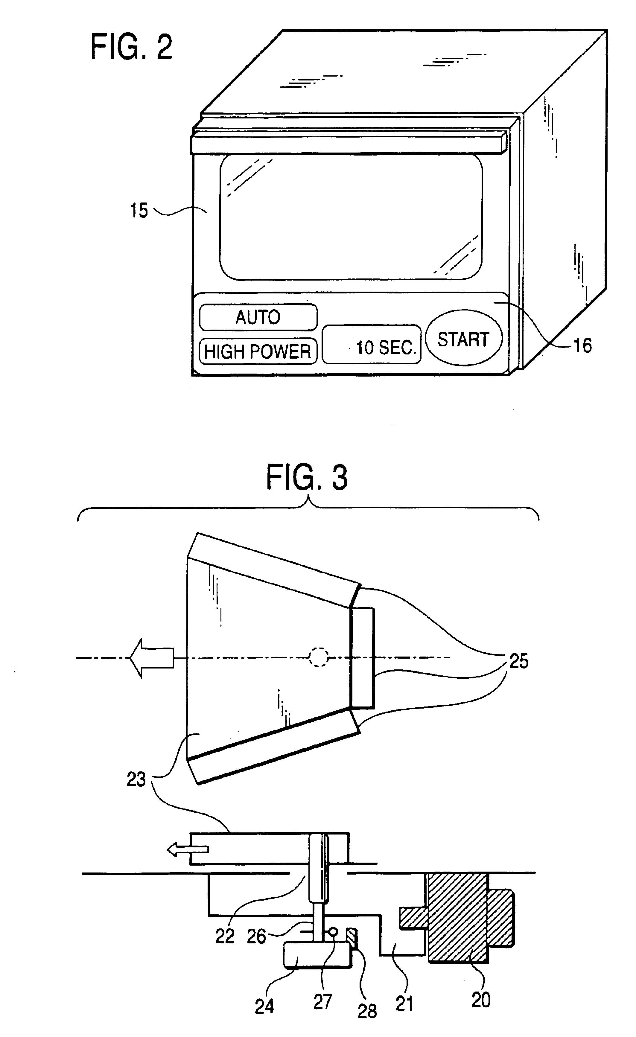
In a perspective view of the heating and cooking apparatus of the present invention shown in FIG. 2, an operating part 16 is provided in the lower part of the door 15 to instruct a selection of menu and a start of heating or the like. On a side surface 17 opposed to the opening part 14 of the heating chamber 10, an opening 18 is provided. A temperature detector 19 is provided near the outsid...


PUM


Abstract

This invention provides a heating and cooking apparatus in which foods can be accommodated in a heating chamber with good maneuverability and an appropriate finish can be obtained. A temperature detector detects infrared radiation through an opening provided on a wall surface opposed to an opening part for taking in and out foods of a heating chamber. The temperature detector detects the temperature of a plurality of parts on a sealing having the substantially same electric wave penetrability as that of the bottom surface of the heating chamber. Accordingly, even when two foods are arranged right and left irrespective of the size of the foods, the temperature of both the foods can be detected. Then, the user does not needs to extend a hand to the interior of the heating chamber and arrange the foods in front and back positions.

Description

BACKGROUND OF THE INVENTION1. Field of the InventionThe present invention relates to a high frequency heating apparatus for heating a material to be heated such as food in which the temperature of the material to be heated is detected to efficiently heat the material to be heated, make a heating distribution uniform and automate a cooking.2. Description of the Related ArtAs such a heating and cooking apparatus, a cooking and heating apparatus has been hitherto disclosed in, for is example, JP-A-2001-250672. FIG. 7 shows the conventional heating and cooking apparatus described in the above-described publication.In FIG. 7, in a microwave range, a bottom plate 1 forms a bottom surface of a heating chamber 2. Microwave oscillated by a magnetron 3 is supplied to a wide area in the heating chamber 2 by a rotary antenna 4. In the microwave range, a method for heating the food in the heating chamber 2 is different depending on a rotating position where the rotary antenna 4 is stopped or a p...

Claims


Application Information

Patent Timeline
IPC IPC(8): H05B6/80H05B6/68F24C7/02H05B6/72H05B6/74
CPCH05B6/6447H05B6/6402
Inventor WATANABE, KENJIKASAI, ISAO
Owner PANASONIC CORP
Why Eureka
Try Eureka