High resolution, multiple detector tomographic radionuclide imaging based upon separated radiation detection elements

a radionuclide imaging and radiation detection technology, applied in tomography, diaphragm/collimeter handling, instruments, etc., can solve the problems of reducing the spatial resolution advantage of using multiple collimator holes, reducing the design complexity of the radionuclide imager, and reducing the density of the collimator hole packing

Inactive Publication Date: 2005-01-04
SIEMENS MEDICAL SOLUTIONS USA INC
View PDF5 Cites 55 Cited by
  • Summary
  • Abstract
  • Description
  • Claims
  • Application Information

AI Technical Summary

Benefits of technology

These and other needs are addressed in the present invention through the use of multiple radionuclide detectors equipped with collimators such that a circular rotation of the detectors around the three-dimensional object to be imaged provides the movement needed for sparse hole or registered collimator sampling. A complete scan of the target is accomplished thr

Problems solved by technology

If the collimator holes are spaced too closely together, the spatial resolution advantage gained by using multiple collimator holes is lost because the intrinsic uniform spatial resolution and energy resolution of the NaI detector blurs the discernable location of a detected radiation emission such that detected radiation emission could have passed through any of several collimator holes.
As a result, the density of the packing of the collimator holes is limited by distance of separation needed by the homogeneous NaI detector to achieve desired spatial resolution.
This requirement for precise motion of the collimator throughout the sampling area adds considerable complexity to the design of the radionuclide imager.
However, the pixel elements are nonhomogeneous in response and tend to have the best performance in the center of the pixel, with poorer performance at the boundaries between pixels.
Like the sparse hole imaging technique, registered collimator scanning generally requires a precise motion of the collimator holes within a two-dimensional plane in order to obtain the usable counts needed to form images, adding considerable complexity to the design of a radionuclide imager using pixellated detector elements.
In an imager having these types of mul

Method used


Image

  • High resolution, multiple detector tomographic radionuclide imaging based upon separated radiation detection elements
  • High resolution, multiple detector tomographic radionuclide imaging based upon separated radiation detection elements
  • High resolution, multiple detector tomographic radionuclide imaging based upon separated radiation detection elements

Examples


Embodiment Construction

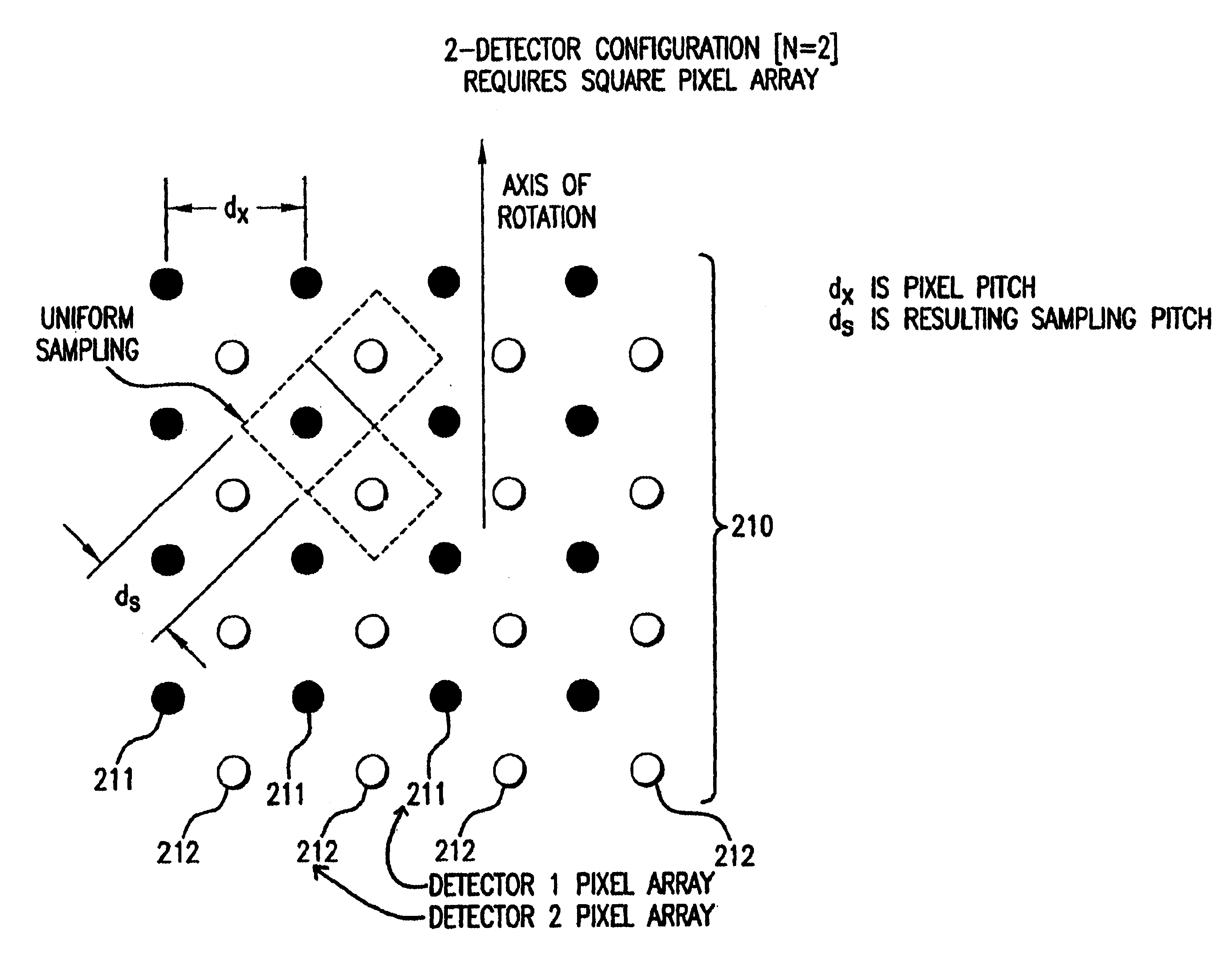
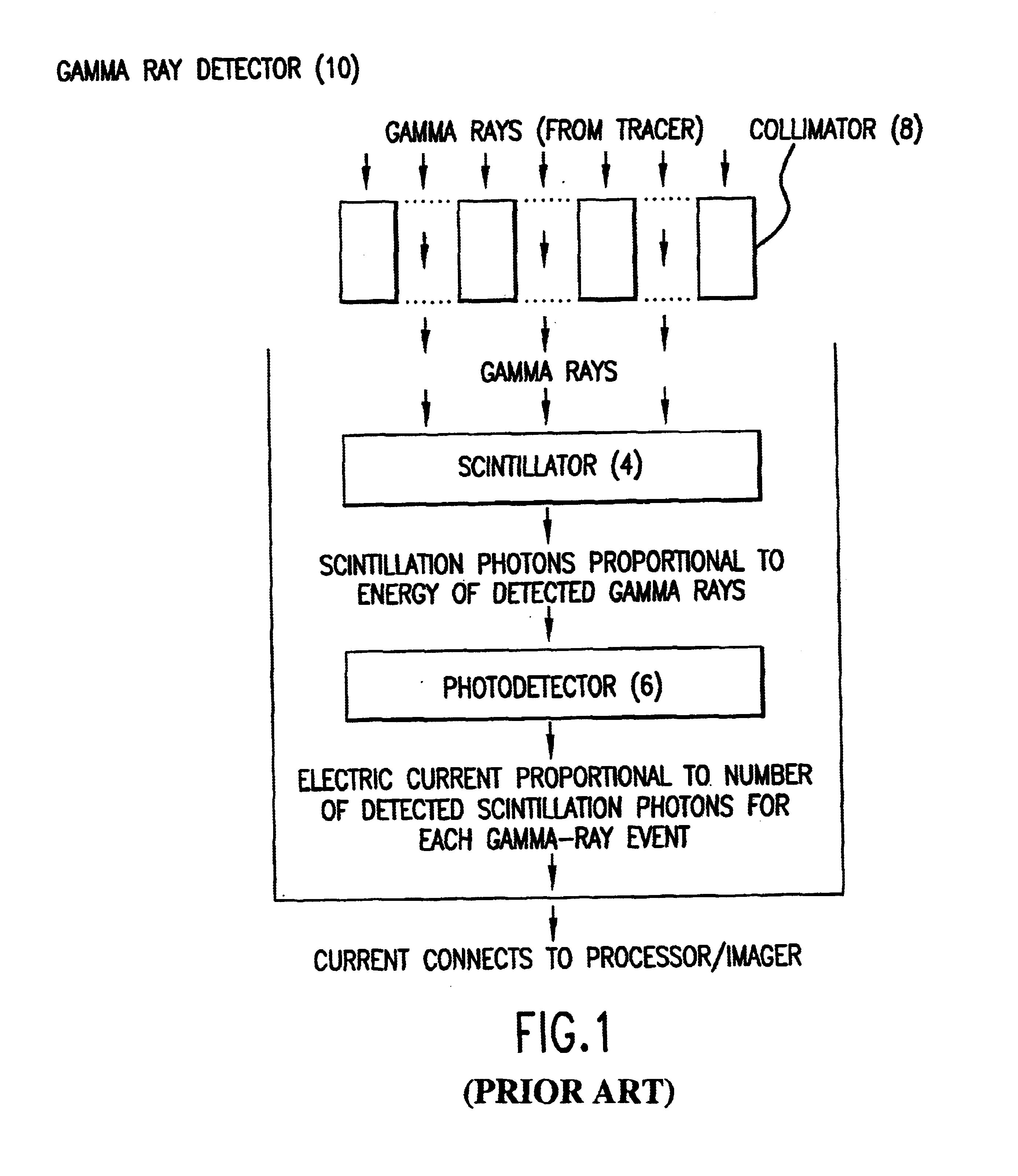
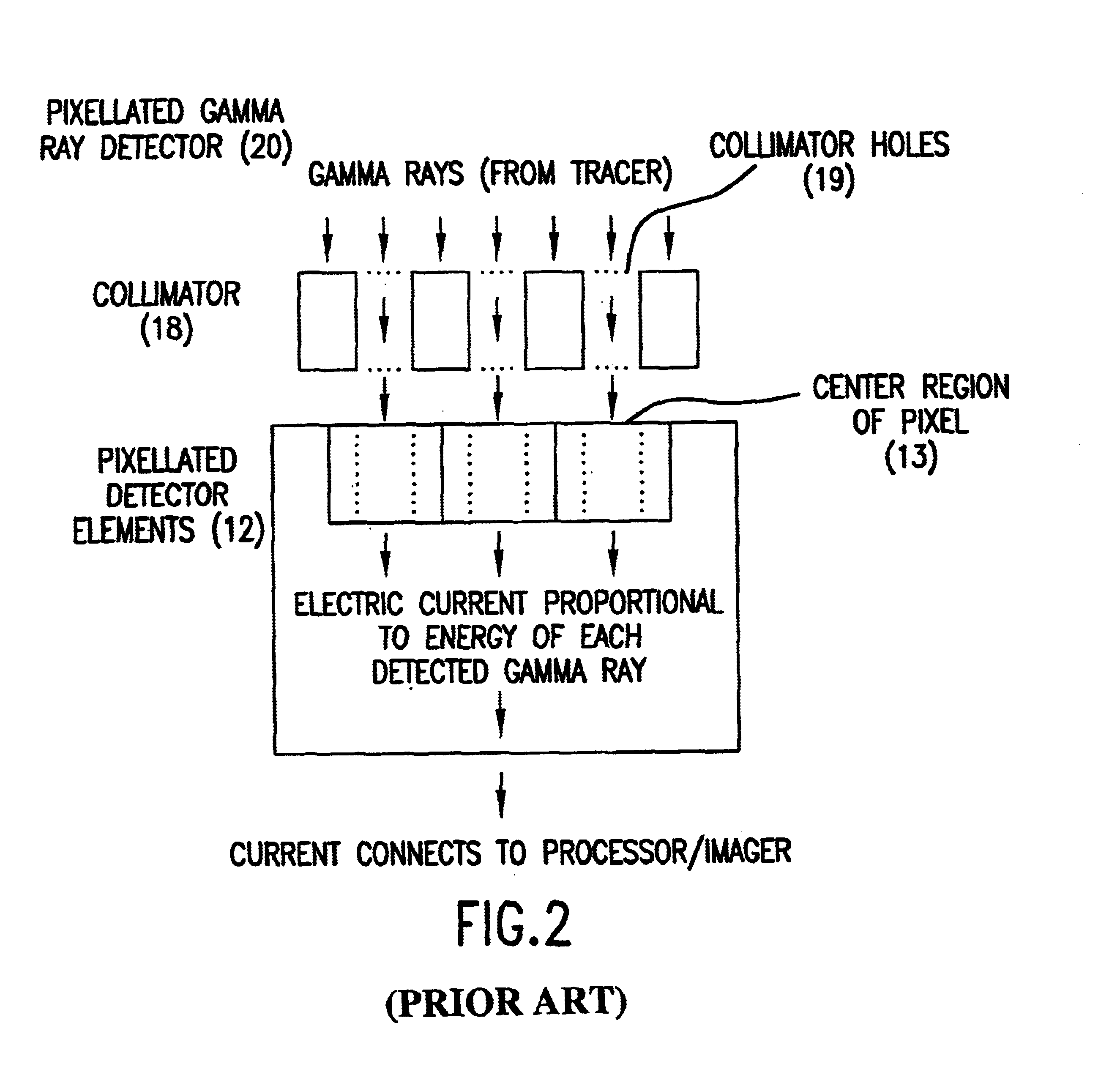
The present invention provides an improved radionuclide imaging device having multiple radiation detectors for scanning three-dimensional targets. The present invention's radionuclide imager generally uses Single Photon Emission Computed Tomography (hereafter “SPECT”) by rotating each detector around the target. In SPECT, the radiation detectors are rotated around the scanned subject to detect and count photon emissions from the radioactive tracer. When the detectors rotate around the scanned object, a lateral axis is defined as the mechanical axis of rotation aligned with a computer matrix for reconstructing the SPECT images. The radionuclide imager then uses the count value obtained by the rotating detectors to reconstruct the distribution of the radioactive tracer in the form of a cross-section image. The rotating detectors may be longitudinally moved relative to the scanned object in order to obtain multiple cross-section images. The multiple cross-section images may then be com...


PUM


Abstract

A radionuclide scanner in which multiple detectors are equipped with collimators such that a circular rotation of the detector around a target provides the movement needed for collimator sampling. This collimator sampling is accomplished through strategic placement of the detector heads relative to each other such that for any given projection, a complete imaging of the projection is acquired by summing the complementary contributions of the multiple detector heads at the projection under consideration.

Description

FIELD OF THE INVENTIONThe present invention relates to an improved radionuclide imaging device having multiple collimated radiation detector elements for scanning three-dimensional targets.BACKGROUND OF THE INVENTIONRadionuclide imaging devices, such as gamma cameras, are used in the medical field to measure radioactive emissions emanating from a subject's body and to form a comprehensible output from these measurements, typically in the form of an image that graphically illustrates the distribution of the emissions within the patient's body. The emissions originate from a decaying radioactive tracer that has been intentionally introduced into the subject's body, and therefore, the image produced by the radionuclide imaging device represents the distribution of the tracer within the subject's body. The radioactive tracer is a pharmaceutical compound to which an electromagnetic radiation emitting nuclide, such as 99mTc, has been attached and which undergoes a physiological process af...

Claims


Application Information

Patent Timeline
IPC IPC(8): G01T1/166G01T1/20G01T1/00G01T1/164
CPCA61B6/037G01T1/1644
Inventor WAGENAAR, DOUGLAS J.PAWLAK, JOHN T.ENGDAHL, JOHN C.
Owner SIEMENS MEDICAL SOLUTIONS USA INC
Why Eureka
Try Eureka