Two-speed rotational control apparatus with eddy current drive

a technology of eddy current drive and rotation control apparatus, which is applied in the direction of dynamo-electric converter control, asynchronous induction clutch/brake, machine/engine, etc., can solve the problems of affecting reliability, affecting the torque capacity of current eddy current drive system used to operate cooling fans, and various problems and deficiencies of coupling drive components

Active Publication Date: 2005-01-04
HORTON
View PDF9 Cites 43 Cited by
  • Summary
  • Abstract
  • Description
  • Claims
  • Application Information

AI Technical Summary

Benefits of technology

Another embodiment of the present invention relates to a rotational control apparatus including a support mount adapted to be maintained in the position fixed against rotation. A first rotatable assembly includes a first portion adapted to be interconnected to a driving source and a second portion axially spaced from the first portion, the second portion further including an outer circumferential surface. A first bearing unit is interposed between the support mount and the first rotatable assembly, with the first rotatable assembly being rotatably supported by the support mount through the first bearing unit. A first engagement surface is provided at the second portion of the first rotatable assembly for concurrent rotation with the first rotatable assembly. The rotational control apparatus includes a second rotatable assembly having first and second sections. The first section of the second rotatable assembly includes a radially extending portion defining an inner radial surface portion aligned with the outer circumferential surface of the first assembly and the inner radial surface portion defining an inner cavity of the second rotatable assembly. The second section of the second rotatable assembly extends radially inwardly from the first section and is axially spaced from the first portion of the first rotatable assembly. A second engagement surface is provided at the first section of the second rotatable assembly. A piston is positi

Problems solved by technology

These coupling drive components suffered from various problems and deficiencies.
The mechanical attachment of the steel and copper rings to the body portion increases the number of components and assembly required and is subject to loosening and/or separating and thereby detrimentally affecting reliability.
Current eddy current drive systems used to operate cooling fans do not have the torque capacity to handle these applications.
Fan dr

Method used


Image

  • Two-speed rotational control apparatus with eddy current drive
  • Two-speed rotational control apparatus with eddy current drive
  • Two-speed rotational control apparatus with eddy current drive

Examples


Embodiment Construction

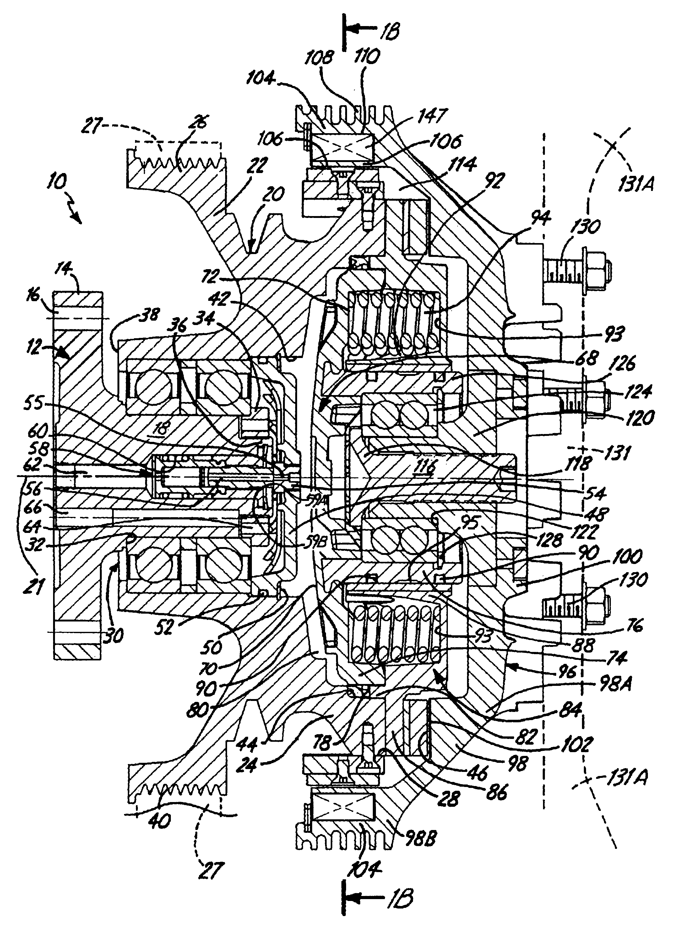
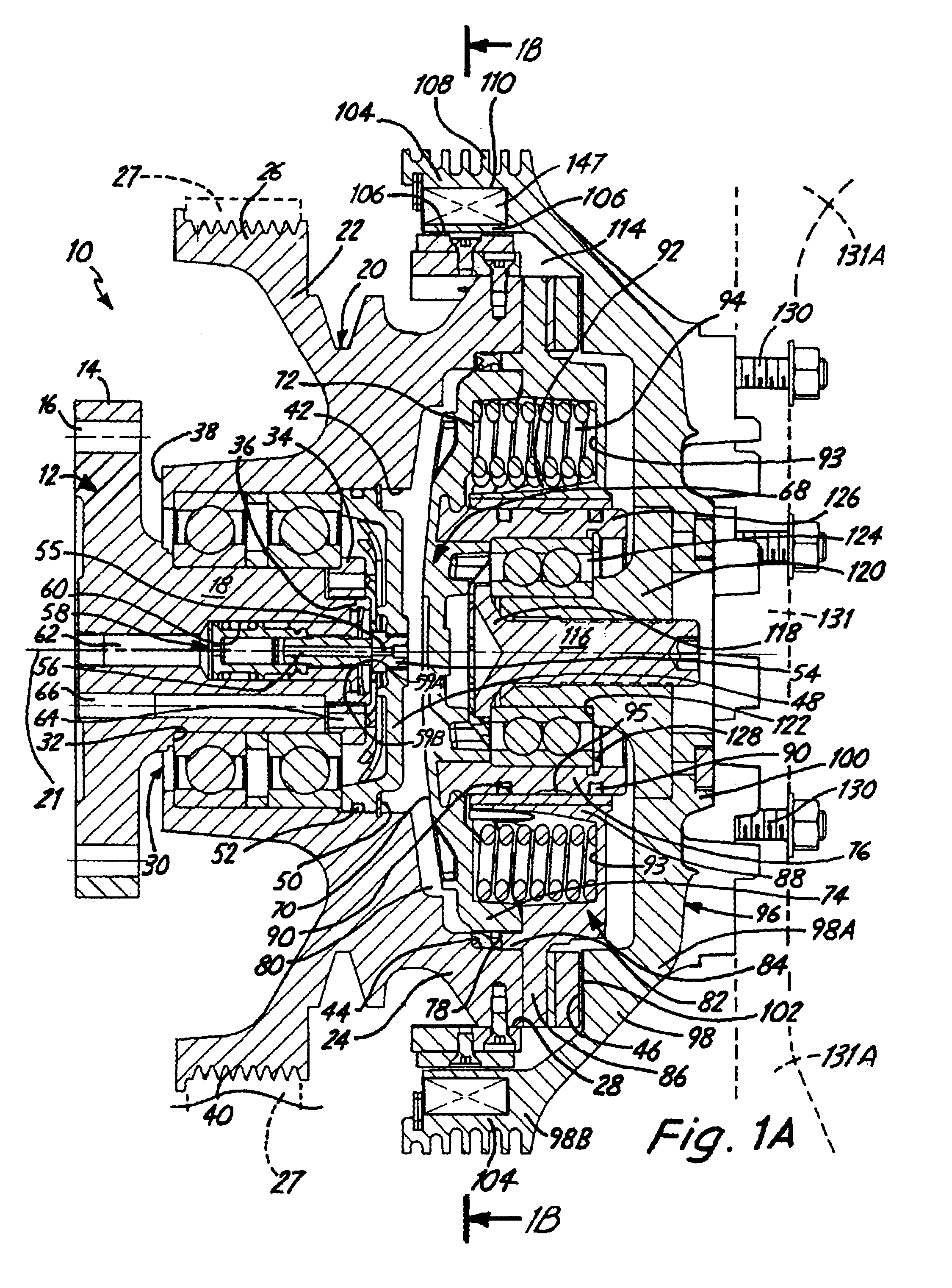
FIG. 1A is a cross sectional view of a rotational control apparatus 10 constructed in accordance with a first embodiment of the present invention. Rotational control apparatus 10 constitutes a friction clutch which is particularly adapted for use in driving a fan at multiple, fixed speeds, such as a cooling fan used in an automotive environment.

Rotational control apparatus 10 includes an integrally formed, support mount 12 for the overall apparatus. Support mount 12 is adapted to be maintained in a position fixed against rotation and includes a flange portion 14 through which a plurality of fasteners (not shown) received within apertures 16 for securing support mount 12 to a supporting structure (not shown), such as an engine block.

Support mount 12 includes a journal shaft 18 that is adapted to support a first rotatable assembly 20. First rotatable assembly 20 includes an axis 21. First rotatable assembly 20 is comprised of a first portion 22 and a second portion 24, axially spaced ...


PUM


Abstract

A rotational control apparatus includes a first rotatable assembly and a second rotatable assembly. The first assembly is rotatably mounted to a first support mount. The second assembly is rotatably mounted to the first assembly and is axially moveable relative to the first assembly. The first and second assemblies have respective coaxial surfaces adjacent to and spaced from one another and further have respective axial surfaces that frictionally engage one another when the second assembly is in a first axial position and disengage when the second assembly is in a second axial position. The second assembly is capable of rotation independent of the first assembly when the second assembly is in the second axial position. The rotational control apparatus includes an eddy current drive comprised of a first eddy current coupling assembly associated with the coaxial surface of the first assembly and a second eddy current coupling assembly associated with the coaxial surface of the second assembly, the second eddy current coupling assembly adjacent the first eddy current coupling assembly with an air gap therebetween.

Description

CROSS-REFERENCE TO RELATED APPLICATION(S)None.BACKGROUND OF THE INVENTIONThe present invention relates to a rotational control apparatus and more particularly to an eddy current fan drive system operable to drive a cooling fan with multiple speed control.In a typical eddy current drive, a first magnetic field producing drive component, such as in the form of permanent magnets, is mounted for rotation with either the input or output of a rotational control apparatus, such as a clutch, for magnetically coupling with a second coupling drive component mounted for rotation with either the input or output. The second coupling drive component was typically in the form of a first ring formed of electrically conductive material, such as copper, sandwiching a second ring of magnetic flux conductive material, such as steel, against a mounting body portion formed of heat conductive material, such as aluminum, so that the body portion acts as a heat sink. Screws extend through the first and seco...

Claims


Application Information

Patent Timeline
IPC IPC(8): F01P7/00F01P7/08F16F15/18F16F15/10H02K49/04H02K49/00
CPCF01P7/081H02K49/043F16F15/18F01P7/082F16D19/00H02K49/02H02K49/04H02P11/00
Inventor NELSON, CHRIS A.
Owner HORTON
Why Eureka
Try Eureka