Method and apparatus for controlling motor

a technology of motor control and control method, applied in the direction of program control, electric programme control, instruments, etc., can solve the problems of difficult control of torque variation, inability to guarantee the accuracy of stop position, and general difficulty in ideal physical operation, etc., to achieve high-speed accurate position control

Inactive Publication Date: 2005-01-04
CANON KK
View PDF42 Cites 39 Cited by
  • Summary
  • Abstract
  • Description
  • Claims
  • Application Information

AI Technical Summary

Benefits of technology

The present invention has been made in consideration of the above situation, and has as its object to provide a method and apparatus for controlling a motor, which can achieve high-speed accurate position control independently of a variation in characteristic due to an individual difference of a motor to be used, attachment of a mechanism, or cogging related to a phase angle.

Problems solved by technology

However, it is difficult to control a torque variation with a short period represented by cogging.
In actual control, however, the ideal physical operation is generally very difficult.
Since this speed cannot satisfy stop conditions required of the apparatus, the stop position accuracy is not guaranteed, and overrun from the stop position may occur.
In this case, however, if the profile has changed to the profile 2007 due to the phase of the motor at the moving start time, the problem that the required time is prolonged becomes more serious.
In this case, however, if the profile has changed to the profile 2006 due to the phase of the motor at the moving start time, the problem that the stop position accuracy is not guaranteed becomes more serious.
However, this period is difficult to accurately detect.
As described above, it is very difficult in fact to set the target speed (V_APPROACH) in the positioning control region in accordance with the cogging characteristic of a DC motor to be used, and to achieve high-speed accurate position control.

Method used


Image

  • Method and apparatus for controlling motor
  • Method and apparatus for controlling motor
  • Method and apparatus for controlling motor

Examples


first embodiment

[First Embodiment]

In the first embodiment, the motor control method of the present invention is applied to control a line feed motor for printing medium conveyance.

FIG. 3 is a perspective view showing the overall arrangement of the serial inkjet printer. Referring to FIG. 3, a printhead 101 has an ink tank. The printhead 101 is mounted on a carriage 102. A guide shaft 103 is inserted to the bearing portion of the carriage 102 so as to be slidable in the main scanning direction. The two ends of the shaft are fixed to a chassis 114. A driving motor 105 serving as a carriage driving means transmits driving power through a belt 104 serving as a carriage drive transmission means engaged with the carriage 102 so that the carriage 102 can move in the main scanning direction.

In a printing standby state, printing paper sheets 115 are stacked on a feed base 106. At the start of printing, a printing paper sheet is fed by a feed roller (not shown). To convey the fed printing paper sheet, a conv...

second embodiment

[Second Embodiment]

The second embodiment of the present invention will be described below. In the second embodiment, the DC motor control method of the present invention is applied to control a line feed motor for printing medium conveyance in a serial inkjet printer, as in the first embodiment. Parts different from the first embodiment will be mainly described below.

In this embodiment, only drive control end processing executed in step S11005 is changed as compared to the first embodiment. The same reference numerals as in the first embodiment denote the same parts below, and a description thereof will be omitted.

FIG. 20 is a flowchart showing drive control end processing of this embodiment in detail. The contents of processing in steps S15001, S15021, S15003, S15011, S15004, S15005, S15012, S15006, and S15013 are the same as those described in the first embodiment with reference to FIG. 15, and a description thereof will be omitted.

Evaluation processing in step S20002 is character...

third embodiment

[Third Embodiment]

The third embodiment of the present invention will be described below. In the third embodiment, the DC motor control method of the present invention is applied to control a line feed motor for printing medium conveyance in a serial inkjet printer, as in the first and second embodiments. Parts different from the above embodiments will be mainly described below.

In this embodiment, only drive control preparation processing executed in step S11002 is changed as compared to the second embodiment. The same reference numerals as in the first and second embodiments denote the same parts below, and a description thereof will be omitted.

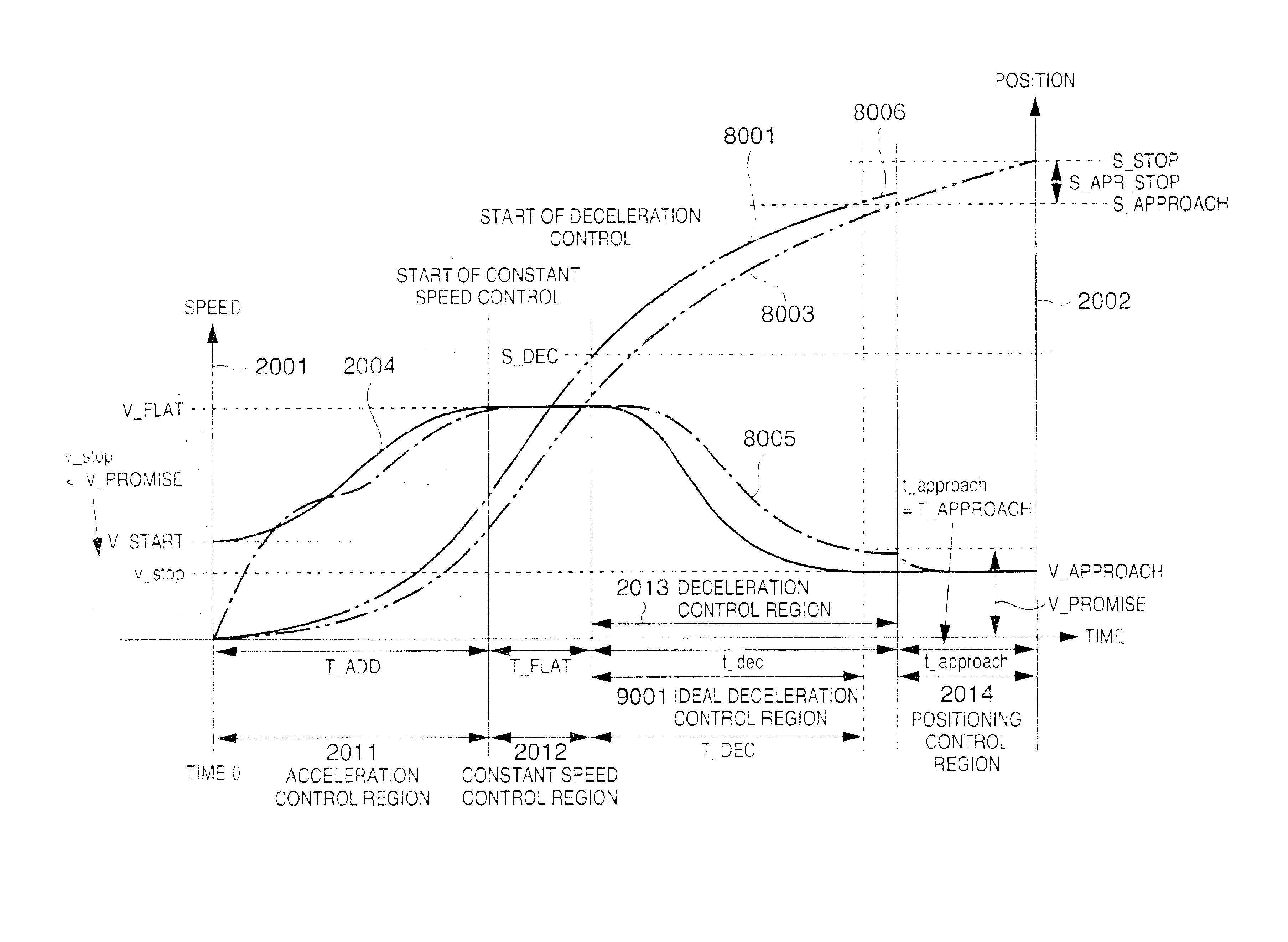
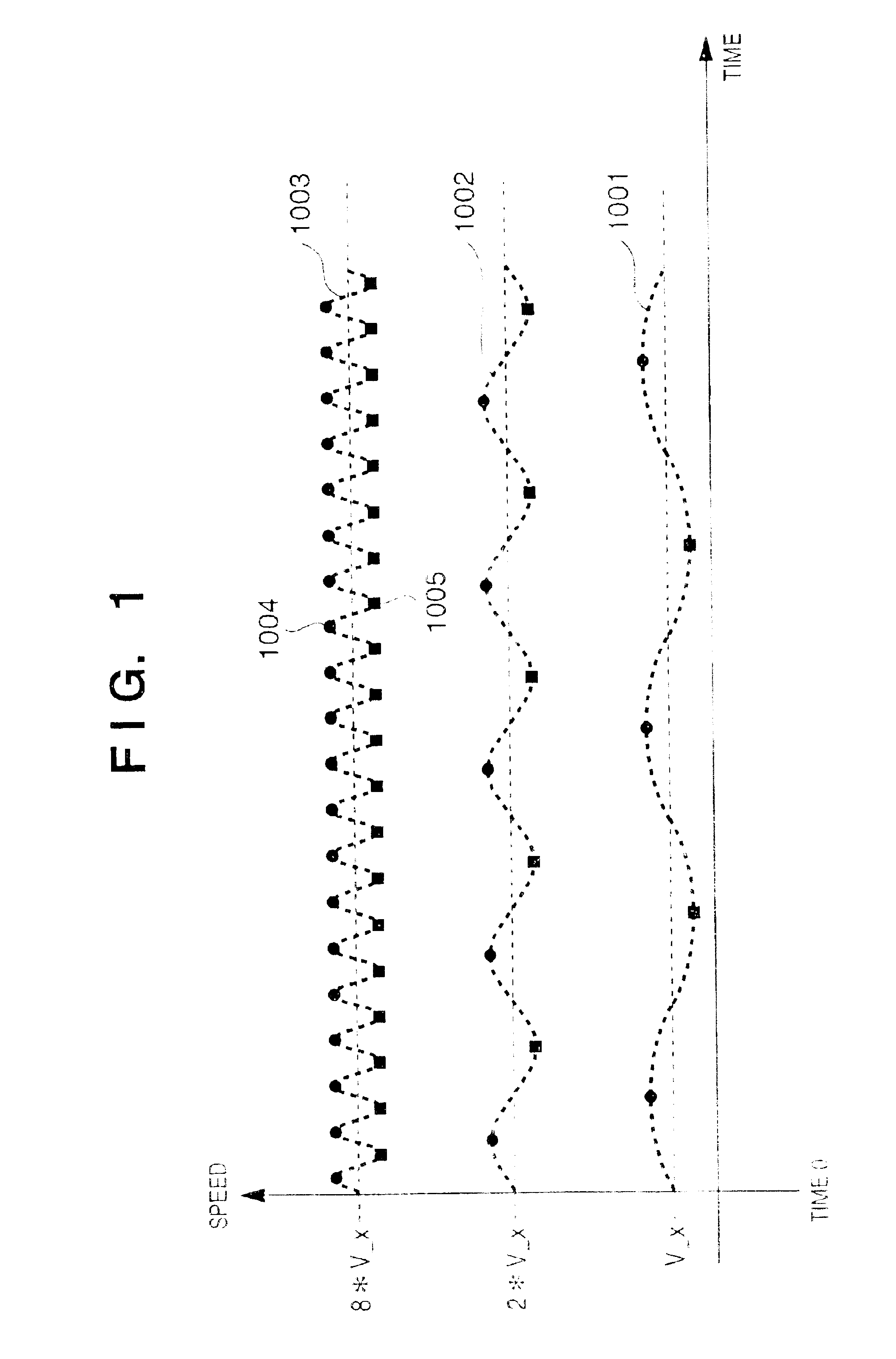
In the second embodiment, it was not clearly described that values s_apr_STOP and v_approach change between a case wherein a position S_STOP corresponds to a point 1004 corresponding to a phase angle at which the motor itself rotates at a high speed due to the influence of a torque variation caused by cogging and a case wherein the position S...


PUM


Abstract

In controlling a motor in a device which drives a mechanism using the motor as a power source, in executing driving, an ideal profile of the driving is generated in accordance with a target position and a preset initial parameter, driving of the motor is controlled in accordance with the profile, the value of the initial parameter is evaluated at the end of driving, and the value of the initial parameter is changed in accordance with the evaluation result. High-speed accurate position control can be achieved independently of the characteristic of an individual motor to be used.

Description

FIELD OF THE INVENTIONThe present invention relates to a method and apparatus for controlling a motor and, more particularly, to positioning executed when a mechanism is driven using a motor as a power source.BACKGROUND OF THE INVENTIONCurrently, motors are used as power sources of various apparatuses. Especially, many OA devices and home electric appliances use DC motors because they have simple structures, require no maintenance, generate little rotation variation and vibration, and are capable of high-speed operation and accurate control.In recent years, printers, and especially general commercial printers that are often for home use, are required to have not only higher image quality but also lower operation noise. Noise generated in operation includes that generated in printing and that generated in driving mechanical portions. In inkjet printing apparatuses which have only a few noise sources in printing, noise generated in driving mechanical portions is reduced.An inkjet prin...

Claims


Application Information

Patent Timeline
Patent Type & Authority Patents(United States)
IPC IPC(8): G05B19/416G05D3/12G05B19/23G05B19/29H02P29/00
CPCG05B19/23G05B19/29G05B19/416G05B2219/45187G05B2219/41329G05B2219/42128G05B2219/43168G05B2219/41115B41J19/202B41J19/207
Inventor KOBAYASHI, NOBUTSUNESHOJI, MICHIHARUSAITO, HIROYUKI
Owner CANON KK
Why Eureka
Try Eureka