Multi-frequency antenna

a multi-frequency antenna and antenna technology, applied in the field of multi-frequency antennas, can solve the problems of affecting the electrical performance, increasing the size of mobile wireless equipment, and substantially incapable of transmission and reception of mobile telephones, so as to prevent the casing from becoming over-sized and prevent the adverse effect of electrical characteristics of multi-frequency antennas

Inactive Publication Date: 2005-01-04
NIPPON ANTENNA CO LTD
View PDF13 Cites 17 Cited by
  • Summary
  • Abstract
  • Description
  • Claims
  • Application Information

AI Technical Summary

Benefits of technology

With the present invention as above, it becomes possible to receive positioning information from a GPS satellite by means of the second antenna for mobile wireless equipment accommodated in the ring-shaped case. Also, since an arrangement can be achieved such that the first antenna for mobile wireless equipment is inserted in a through-hole formed in substantially the center of the ring-shaped case, the multi-frequency antenna can be arranged in the upper part of the casing, thereby making it possible to prevent the casing becoming over-sized. Also, thanks to the arrangement thereof in the upper part of the casing, there is little likelihood of the multi-frequency antenna being covered by the hand of the user holding the equipment, so adverse effects on the electrical characteristics of the multi-frequency antenna can be prevented.

Problems solved by technology

However, since, when the whip antenna is accommodated in the casing, the mobile telephone is substantially incapable of transmission and reception, a helical antenna comprising a small coil element that is positioned outside the casing even when the whip antenna is accommodated in a casing may be provided at the tip of the whip antenna.
However, in order to achieve a construction that is capable of operation with a plurality of communication systems including the GPS system in a single item of mobile wireless equipment, it was necessary for example to incorporate a planar antenna for GPS or to install a small-volume chip antenna in the casing, in addition to the antenna 300 for the mobile wireless equipment, as shown in FIG. 11 described above; this therefore led to the problem of tending to increase the size of the mobile wireless equipment.
Also, there is the problem that, since the mobile wireless equipment is employed held in the user's hand, if a GPS antenna is provided in the casing, the proportion of the GPS antenna that is covered by the hand of the user holding the equipment becomes large, adversely affecting the electrical performance.

Method used


Image

  • Multi-frequency antenna
  • Multi-frequency antenna
  • Multi-frequency antenna

Examples


Embodiment Construction

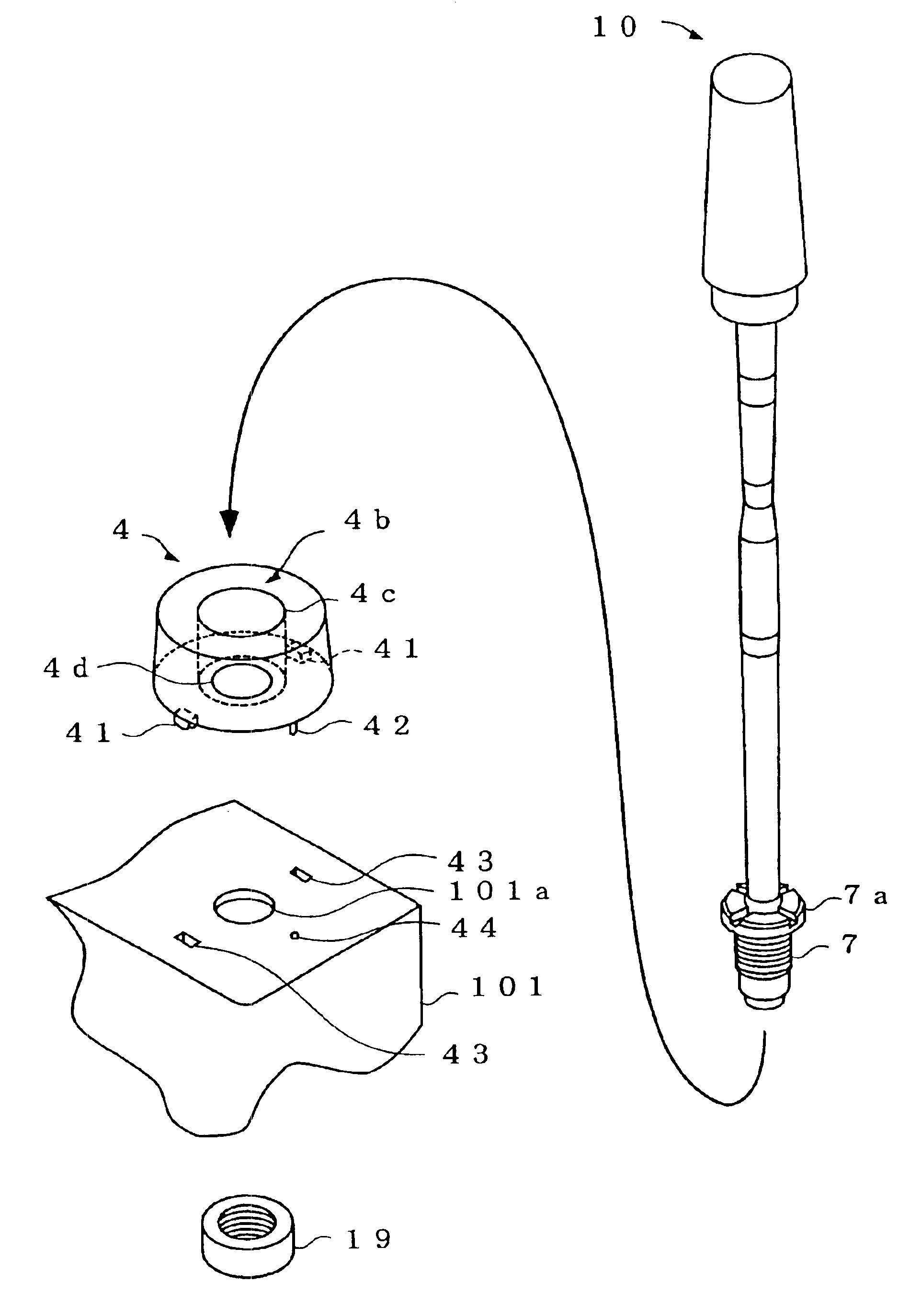
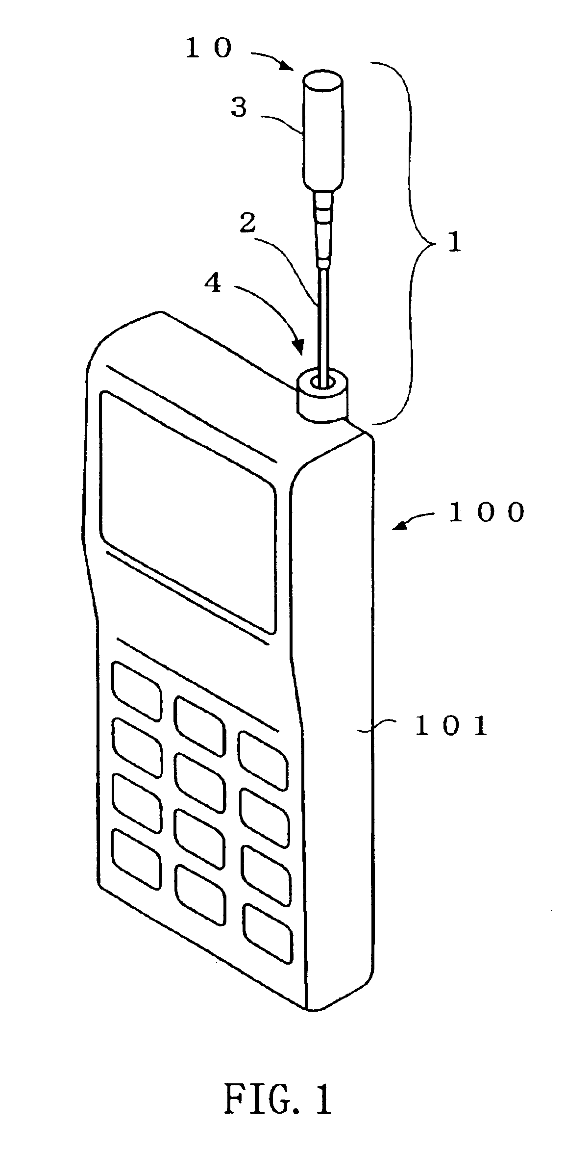
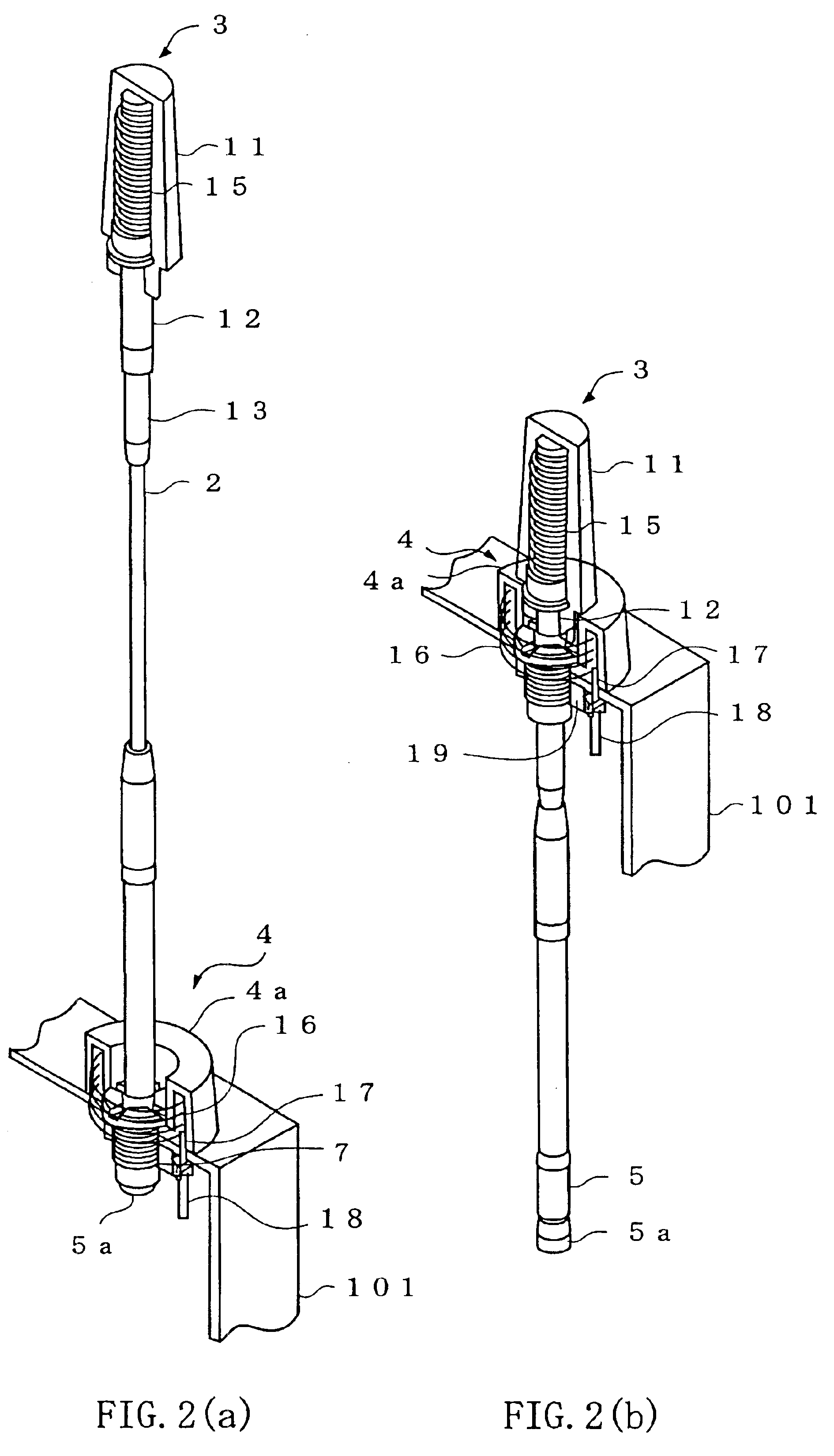
FIG. 1 shows the construction of mobile telephone equipment comprising a multi-frequency antenna according to an embodiment of the present invention. FIG. 2 to FIG. 4 show the construction of a multi-frequency antenna according to an embodiment of the present invention.

A mobile telephone 100 shown in FIG. 1 comprises a casing 101 in which a telephone functional circuitry section and / or battery are accommodated; various buttons including a dialing button and a display are provided on the front face of the casing 101. An antenna 1 for multi-frequency use according to an embodiment of the present invention is provided on the upper face of the casing 101.

The antenna 1 for multi-frequency use comprises an antenna 10 for the mobile wireless equipment and a GPS antenna 4. The antenna 10 for the mobile wireless equipment is constructed so as to operate as a substantially non-directional monopole antenna in the horizontal plane and is provided in the mobile telephone 100 in order to perform ...


PUM


Abstract

With the object of providing a mobile wireless equipment with a multi-frequency antenna capable of performing communication with a GPS system in addition to conventional communication with mobile wireless systems, an antenna 10 for mobile wireless equipment and a GPS antenna 4 are tightened together by threading an antenna fixing nut 19 onto a holder 7 from within a casing 101, after inserting a holder 7 of the antenna 10 for mobile wireless equipment from above a through-hole 4b of the GPS antenna 4 and inserting the holder 7, which projects from below, from above into an aperture 101a of the casing 101. Also, positioning and fixing of the GPS antenna 4 are performed by engagement of claws 41, 41 formed on the GPS antenna 4 and a positioning boss 42 with claw receiving sections 43, 43 and a boss receiving section 44 formed in the upper part of the casing 101.

Description

TECHNICAL FIELDThe present invention relates to a multi-frequency antenna provided in mobile wireless equipment such as a mobile telephone.BACKGROUND ARTRecently, mobile wireless equipment such as mobile telephones has become common; such a mobile telephone is provided with an antenna for transmitting and receiving calls and / or information. Typically, this antenna is in the form of a whip antenna that can be freely extended / retracted and that can be accommodated in the casing of the mobile telephone for convenience in carrying when the mobile telephone is on standby.However, since, when the whip antenna is accommodated in the casing, the mobile telephone is substantially incapable of transmission and reception, a helical antenna comprising a small coil element that is positioned outside the casing even when the whip antenna is accommodated in a casing may be provided at the tip of the whip antenna. In this way, when the whip antenna is accommodated in the casing, transmission and re...

Claims


Application Information

Patent Timeline
Patent Type & Authority Patents(United States)
IPC IPC(8): H01Q1/10H01Q5/00H01Q1/24H01Q21/28H01Q21/00H01Q1/08H01Q21/30H04B1/38H04B1/3822H04M1/02
CPCH01Q1/10H01Q5/342H01Q21/28H01Q1/244H01Q1/24H01Q21/30
Inventor SHIMABARA, MASATAKAMAKINO, MITSUYA
Owner NIPPON ANTENNA CO LTD
Why Eureka
Try Eureka