
Spectral optimization for communication under a peak frequency-domain power constraint

a power constraint and spectral optimization technology, applied in the field of electronic communication, can solve problems such as spectral compatibility, reducing the capacity of the hdsl2 service, and a large amount of crosstalk interferen

Inactive Publication Date: 2005-01-04
RICE UNIV
View PDF16 Cites 177 Cited by
  • Summary
  • Abstract
  • Description
  • Claims
  • Application Information

AI Technical Summary

Benefits of technology

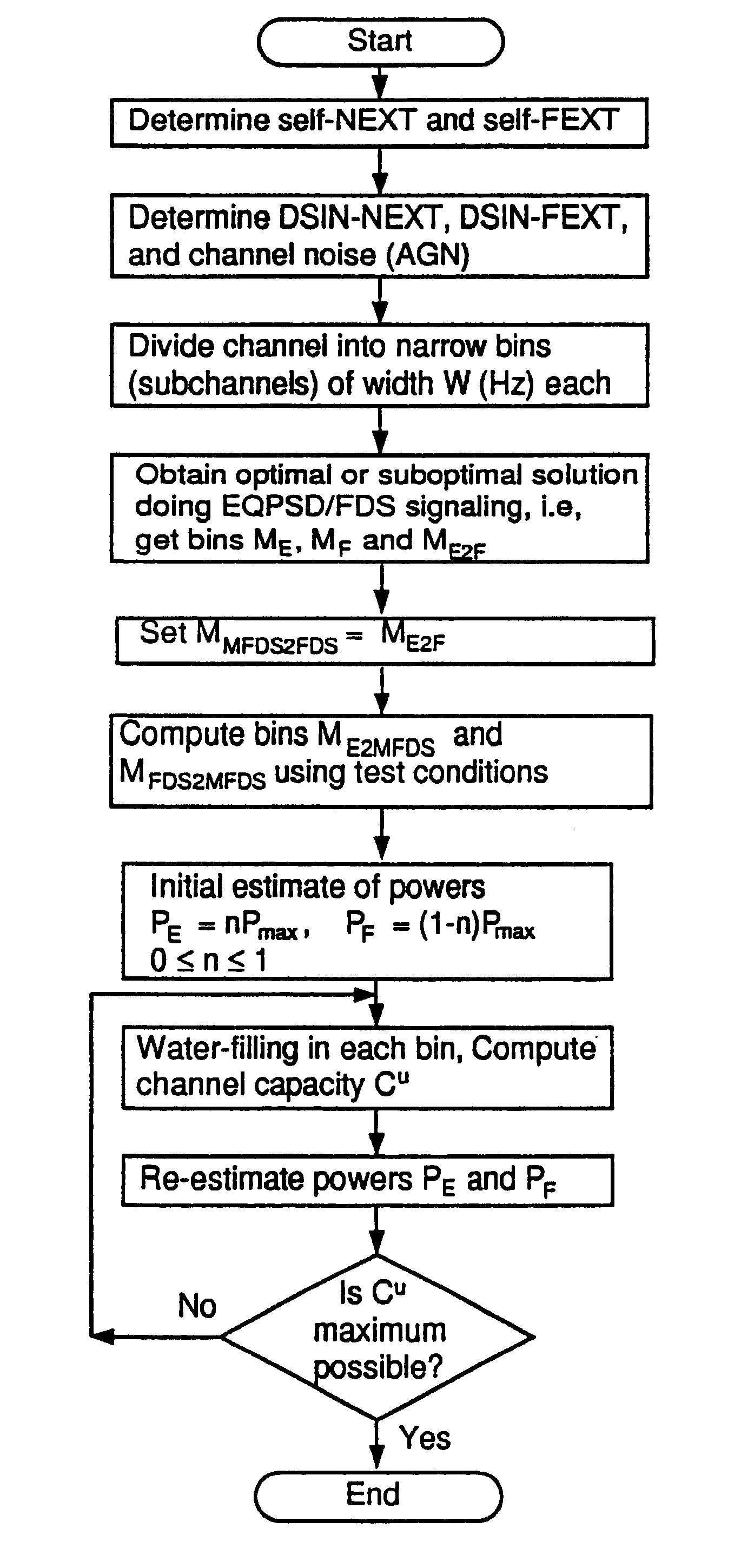
The patent describes methods for optimizing transmit spectra for digital communication channels that experience cross-talk and interference. The methods allocate largely contiguous frequency bands to each signaling direction on each channel, and determine interference characteristics of the channels. The optimized transmit spectra include portions of the frequency spectrum where upstream and downstream transmission are orthogonally separated from each other. The methods also re-distribute the bins so that wider frequency bands are available for signaling in each channel. The patent also describes a method for communicating data on a channel limited by a peak power constraint. The transmit spectra are determined to maximize the capacity of the channels, while minimizing the effects of interference. The technical effects of the patent include improved signal quality, increased data transmission capacity, and reduced interference between signals.

Problems solved by technology

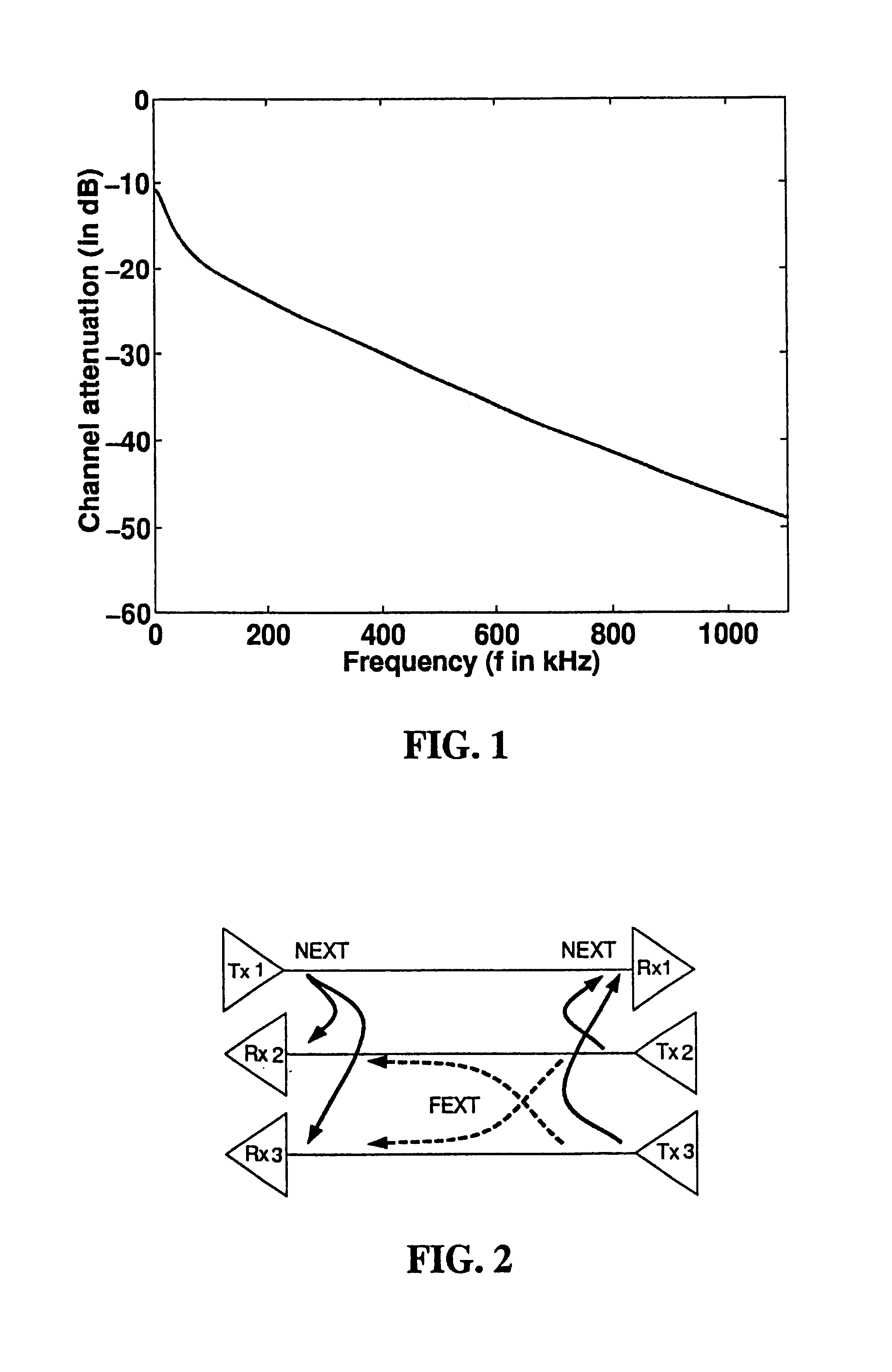
Due to the close proximity of the lines within a binder, there is considerable amount of crosstalk interference between different neighboring telephone lines.
In a real system, however, Tio's signal leaks into the receivers Rjō and Rjo.
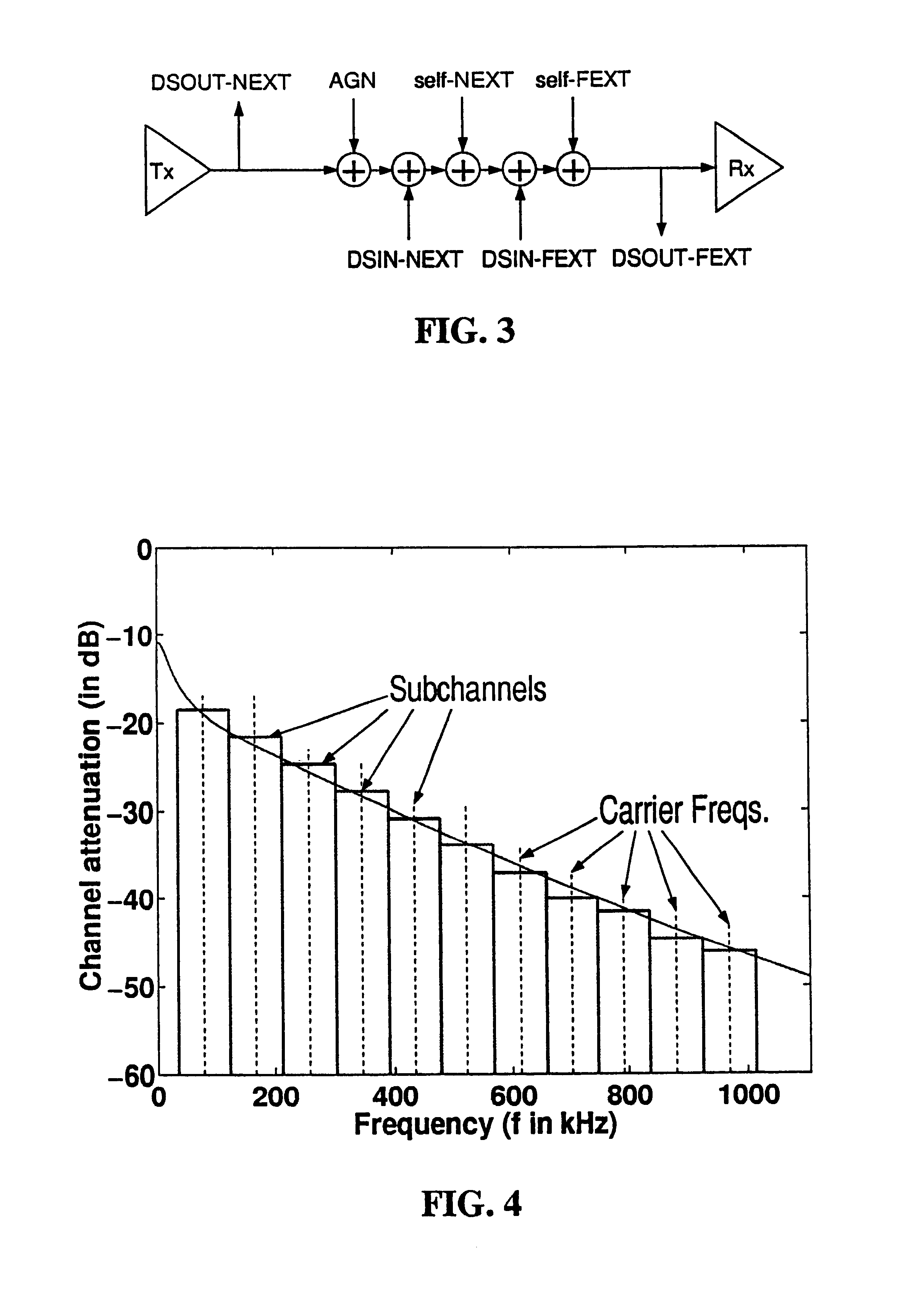
All previously proposed schemes for HDSL2 achieve the required data rates with satisfactory margins only in complete isolation. However, due to the proximity of the lines in a cable, there is considerable DSIN-NEXT, DSIN-FEXT, self-NEXT and self-FEXT interference from T1, ISDN, HDSL, ADSL and HDSL2 into HDSL2—this interference reduces the capacity of the HDSL2 service. Simultaneously, there is considerable DSOUT-NEXT and DSOUT-FEXT interference from HDSL2 into T1, ISDN, HDSL and ADSL.
This problem is known as spectral compatibility.
No prior system has been developed that systematically optimizes the HDSL2 spectrum and reduces interference effects both from and into HDSL2.
Further, a modulation scheme for HDSL2 has not been decided upon at this time.
Further, in CDS each service occupies the entire available bandwidth for all of the time.
Since in a typical system FDS cuts the bandwidth available to each transmitter to ½ the overall channel bandwidth, we have an engineering tradeoff: FDS eliminates self-NEXT and therefore increases system capacity; however, FDS also reduces the bandwidth available to each transmitter / receiver pair and therefore decreases system capacity.
The scheme in [3] is optimized, but only for an over simplified scenario (and therefore not useful in practice).
In particular, [3] does not address self-FEXT and interference from other lines as considered in this work.
Further, [3] does not address spectral compatibility issue.
Note, however, that multitone modulation is definitely not the only modulation scheme that can be used to implement (optimal) transmit spectra.
However, these schemes by no means optimize the capacity of the services considered.An optimal signaling scheme has been developed in [3] for the case of self-NEXT and white additive Gaussian noise only.
The development of [3] does not address crosstalk from other sources, such as DSIN-NEXT and DSIN-FEXT, or self-FEXT, or other types of additive Gaussian noise.
The development of [3] also does not address spectral compatibility of the designed service with respect to other services.

Method used


Image

  • Spectral optimization for communication under a peak frequency-domain power constraint
  • Spectral optimization for communication under a peak frequency-domain power constraint
  • Spectral optimization for communication under a peak frequency-domain power constraint

Examples


case 2

and in Case 2 as c1u⁡(Case⁢ ⁢2)=W2⁢ln⁢ ⁢2⁢{ln⁡[1+S2⁢Y+Z+N]+ln⁡[1+SZ+N]}.(36)

Compute the capacity differences in the two cases as D=c1u⁡(Case⁢ ⁢2)-c1u⁡(Case⁢ ⁢1)=W2⁢ln⁢ ⁢2⁢ln⁡[(1+S2⁢Y+Z+N)⁢(1+SZ+N)(1+SY+Z+N)2].(37)

Taking the partial derivative of D with respect to Y we get ∂D∂Y=Wln⁢ ⁢2⁢S⁡[1(Y+Z+N)⁢(Y+Z+N+S)-1(2⁢Y+Z+N)⁢(2⁢Y+Z+N+S)].

Let

U=Y+Z+N,

V=Y+Z+N+S.

Note that U, V≧0 and that we can rewrite the partial derivative of D with respect to Y as ∂D∂Y=Wln⁢ ⁢2⁢S⁡[1UV-1(U+Y)⁢(V+Y)]=Wln⁢ ⁢2⁢S⁡[Y2+(U+V)⁢YUV⁡(U+Y)⁢(V+Y)]≥0.(38)

Further, ∂D∂YY=0=0.

The slope of D with respect to Y is always positive and hence, c1u(Case 2)−c1u(Case 1) is always increasing with Y, which implies that

c1u(Case 2)−c1u(Case 1) ∀Y≧0.

When Y<0, i.e., when FEXT is higher than NEXT in a bin (F>X), we can redefine Y and Z as

Z=2aX, and, Y=a(F−X).

We can then follow the same analysis and show that the capacity c1u(Case 2) is greater than c1u(Case 1).

Thus, we have proven that FDS scheme rather than CDS scheme for interfering l...


PUM


Abstract

System and methods for determining an optimized transmit spectra (spectral distributions of transmission power) for a set of communications channels that experience cross-talk among themselves and for transmitting data on the channels. The transmit spectra are preferably constructed so that largely contiguous frequency bands are allocated to each signaling direction (upstream / downstream) on each communications channel and / or to each channel in the set of channels. In one embodiment, each communications channel is restricted to a maximum time-averaged power. The method preferably includes steps of determining the channel transfer functions of the communications channel, determining interference characteristics of the channels, calculating substantially optimal transmit spectra for the communications channels, and redistributing the frequency bins so that they are contiguously grouped in each transmit spectra. The contiguous groupings allow wider frequency bands for signaling in the channel. In one embodiment, the channel is limited by a “peak-power constraint.”

Description

MICROFICHE APPENDIXThis application includes a CD appendix. The appendix comprises a source code listing of a preferred embodiment of the invention. A hard copy of the appendix is also submitted herewith.FIELD OF THE INVENTIONThe invention relates to electronic communication and, more particularly, to techniques for communicating on communications channels subject to interference such as cross talk and noise.OUTLINEDescription of the Related Art1 Communications Background1.1 Twisted pairs1.2 Overview of services1.3 Crosstalk interference1.3.1 NEXT and FEXT1.3.2 Notation for self-NEXT and self-FEXT1.4 Capacity and performance margin2 Problem Statement2.1 General statement2.2 Particular statement for DSLs2.2.1 HDSL2 service2.2.2 “GDSL” service2.2.3 “VDSL2” service3 Previous Work3.1 Static PSD Masks and transmit spectra3.2 Joint signaling techniques3.3 Multitone modulation3.4 Summary of previous workSummary of the InventionBrief Description of the DrawingsDetailed Description of the Pr...

Claims


Application Information

Patent Timeline
Patent Type & Authority Patents(United States)
IPC IPC(8): H04L5/14H04L27/26H04L27/00
CPCH04L5/14H04L27/2614H04L27/2608H04L27/00H04W52/346H04L27/2646
Inventor GAIKWAD, ROHIT V.BARANIUK, RICHARD G.
Owner RICE UNIV
Learn More