
Tunable optical filtering device and method

a filtering device and optical filter technology, applied in the field of optical filters, can solve the problems that the most known implementations of scanning filters fail to meet the requirements of specifications

Inactive Publication Date: 2005-01-04
LAMBDA CROSSING
View PDF17 Cites 39 Cited by
  • Summary
  • Abstract
  • Description
  • Claims
  • Application Information

AI Technical Summary

Benefits of technology

"The present invention provides a novel tunable optical filter device and method for processing a multi-frequency light signal to separate therefrom a predetermined frequency component. The filter device has an input for receiving the input light signal, a first output for outputting a first light component of the input light signal, a second output for outputting a second light component, and an intermediate input. The filter device can be used in conjunction with a tunable frequency-selective optical unit to further separate the predetermined frequency component. The invention also provides a complimentary two-stage filtering method where the parameters of the second stage filter are defined independently. The technical effects of the invention include improved filtering of multi-frequency light signals, improved separation of predetermined frequency components, and relaxed tuning range of the filter."

Problems solved by technology

However, most of the known implementations of scanning filters fall short of fulfilling the required specifications, because of inherent material physical limitations.

Method used


Image

  • Tunable optical filtering device and method
  • Tunable optical filtering device and method
  • Tunable optical filtering device and method

Examples


Embodiment Construction

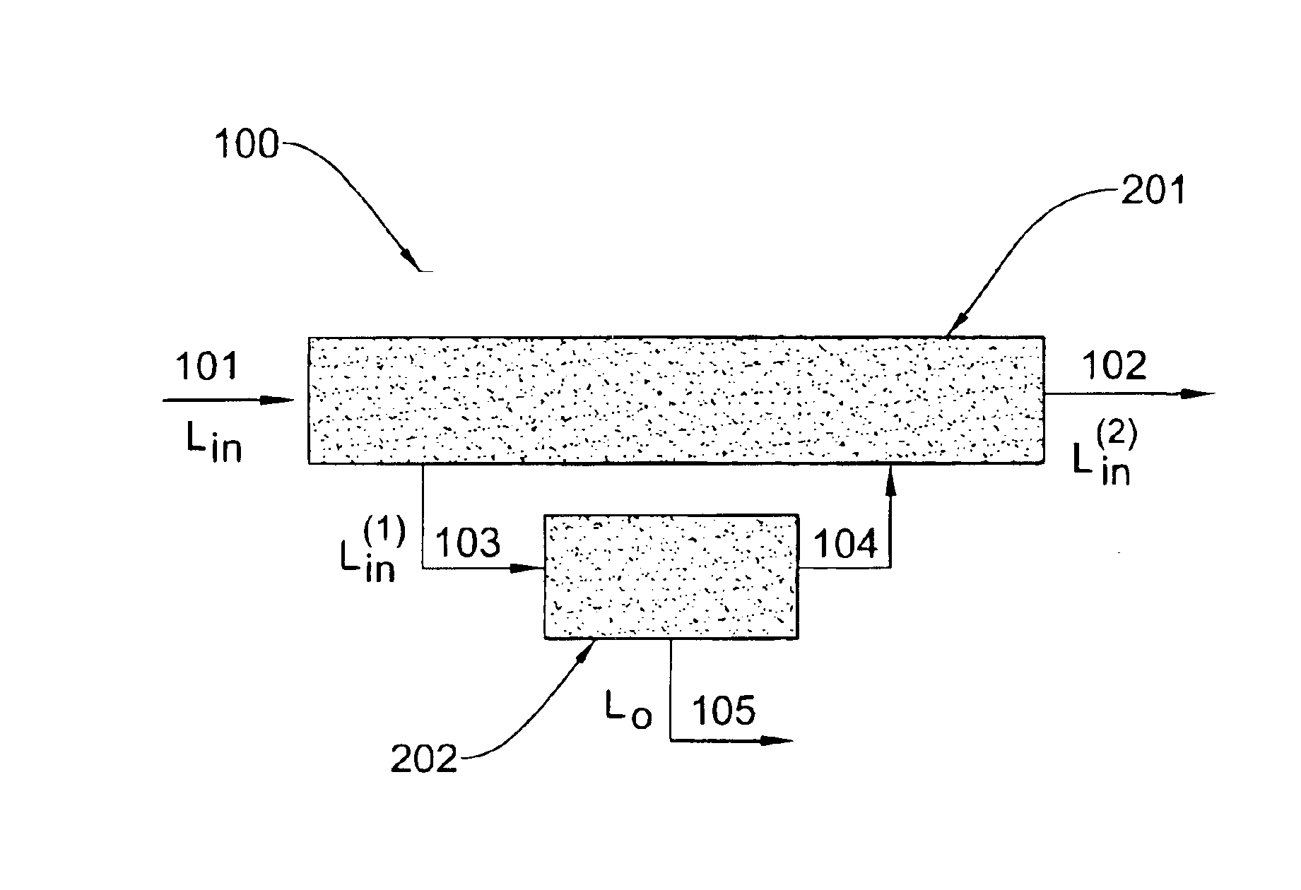
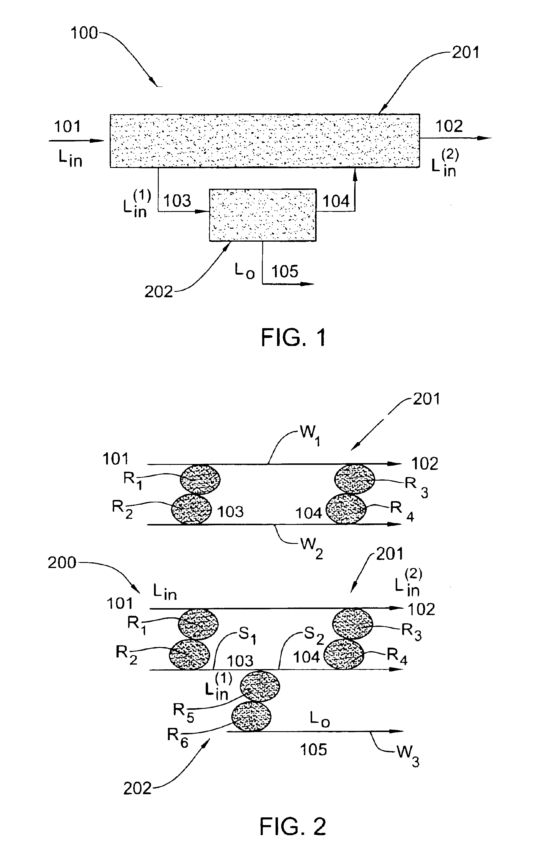
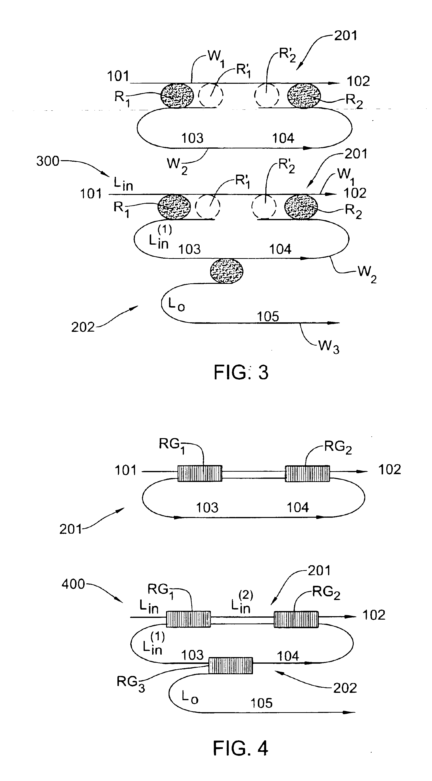
Referring to FIG. 1, there is illustrated a tunable filter structure 201 according to the invention connectable to a tunable frequency selective optical unit 202. The optical unit may be a filter structure, amplifier, attentuator, etc. The filter structure 201 has one input associated with an input light-path 101, a first output associated with a light-path 103, a second output associated with a light-path 102, and an intermediate input associated with a light-path 104. The second output and intermediate input of the structure 201 serves for connecting to, respectively, the input and output of the optical unit 202.

In the present example, the optical unit 202 is a filter structure. A combination of the filter structures 201 and 202 connected to each other as described above thus presents a tunable optical filter device 100 according to the invention, wherein the tunable filter structures 201 and 202 serve as first-stage (first-layer) and second-stage (second-layer) tunable filters, r...


PUM


Abstract

A tunable filter structure, and an optical method and device utilizing the same are presented for processing a multi-frequency light signal to separate therefrom a desired frequency range. The filter structure has an input for receiving the multi-frequency input light signal, a first output for outputting a first light component of the input light signal including light of said predetermined frequency range, a second output for outputting a second light component including a remaining portion of the input light signal, and an intermediate input. The first output and the intermediate input of the filter structure may be connected to, respectively, input and output of a tunable frequency-selective optical unit, which may be a second filter structure, amplifier, attenuator. By using the second filter structure with a different tuning range as compared to that of the first filter structure such that these tuning ranges define overlapping spectra of the filter structures, a two-stage filter device is provided.

Description

FIELD OF THE INVENTIONThis invention is generally in the field of optical devices for use in optical communication systems, and relates to a wavelength selective tunable filtering device and method, particularly useful for adding or dropping channels in a wavelength division multiplexing (WDM) system.BACKGROUND OF THE INVENTIONOptical transmission systems, which are based on wavelength division multiplexing (WDM), achieve high information capacities by aggregating many optical channels, each with a unique carrier frequency, onto a signal strand of optical fiber. Tunable filters play a critical role in WDM communication systems. A tunable filter, which can redirect and route light signals of certain wavelengths (channels), is used:in conjunction with a tunable laser to create a tunable transmitter,midway in the fiber in wavelength for add and drop multiplexing applications,at the receiving end in conjunction with a broad band detector for a tunable receiver.In applications utilizing ...

Claims


Application Information

Patent Timeline
Patent Type & Authority Patents(United States)
IPC IPC(8): G02B6/34H04Q11/00G02B6/12H04J14/02
CPCG02B6/29319G02B6/29343H04Q11/0005G02B6/29395G02B2006/12109H04Q2011/0018H04J14/0206H04J14/021H04Q2011/0009G02B2006/12164
Inventor MARGALIT, MOTI
Owner LAMBDA CROSSING
Learn More