

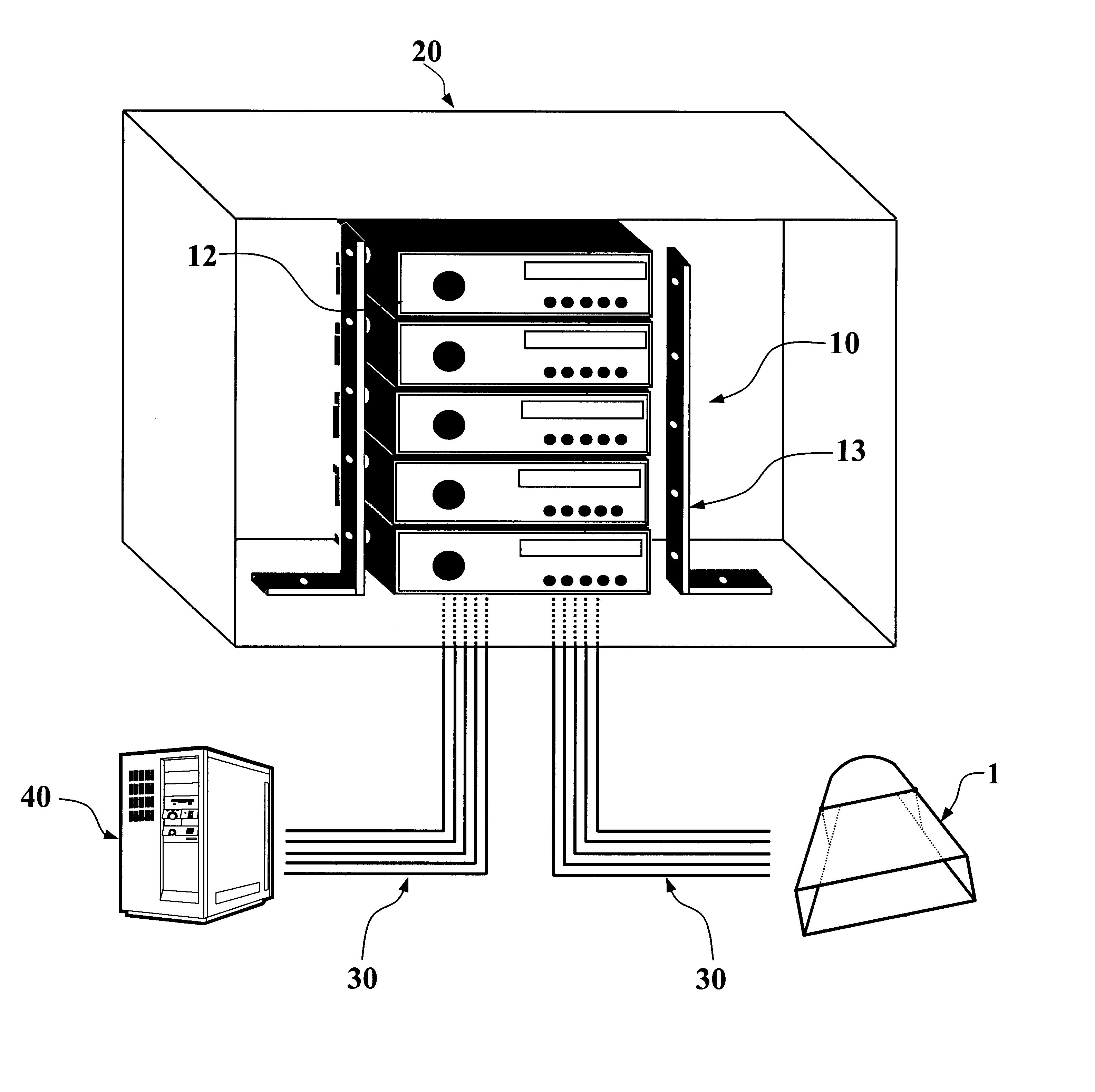
RF shielding design for wireless high-speed internet access system
a high-speed internet access and shielding design technology, applied in the direction of substation equipment, wireless communication, standard structures, etc., can solve the problems of increasing demand beyond capacity, increasing downward cost pressure, and relationally low cost per channel serviced, so as to improve shielding design, reduce cost, and reduce cost
- Summary
- Abstract
- Description
- Claims
- Application Information
AI Technical Summary
Benefits of technology
Problems solved by technology
Method used
Image

Examples
Embodiment Construction
The present invention will now be described more fully, hereinafter, with reference to the accompanying drawings, in which preferred embodiments of the invention are shown. This invention may, however, be embodied in many different forms and should not be construed as limited to the embodiments set forth herein. Rather, these embodiments are provided so that this disclosure will be thorough and complete, and will fully convey the scope of the invention to those skilled in the art. Like numbers refer to like elements throughout.
A type of radio technology known as Spread Spectrum Frequency Hopping, (SSFH) has recently become popular in the industry to deliver wireless Internet access. Frequencies set aside by the FCC and ETSI, known as ISM (Industrial Scientific and Medical) in the 2.4 GHz and 900 MHz bands, have become the de facto standard for such services. These services operate under FCC part 15, unlicensed use, and as such must exist with certain technological hobbles imposed by...
PUM
 Abstract
Description
Claims
Application Information