
Apparatus, method, and program for implementing garbage collection suitable for real-time processing

a garbage collector and real-time processing technology, applied in data processing applications, multi-programming arrangements, memory allocation/allocation/relocation, etc., can solve the problems of inability to complete the required processing within the predetermined time, difficult to predict when and how long the garbage collector interrupts the application program, and none of the conventional techniques are suitably applied to the application program

Active Publication Date: 2005-01-04
PANASONIC CORP
View PDF8 Cites 32 Cited by
  • Summary
  • Abstract
  • Description
  • Claims
  • Application Information

AI Technical Summary

Benefits of technology

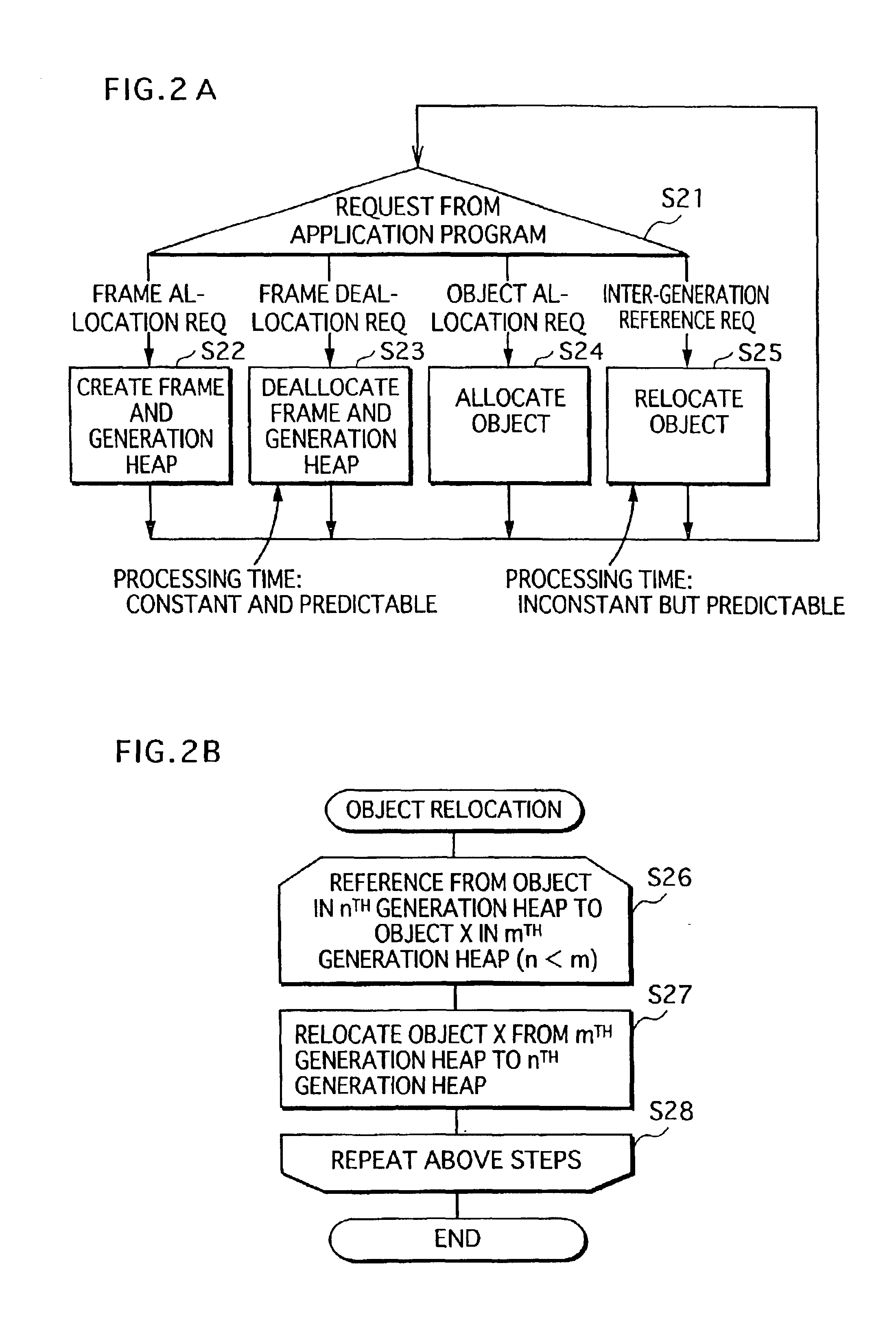
[0023]As stated above, the garbage collector takes a relatively short time to complete main processing, such as deallocation of a memory area, and relocation of an object. In addition, the time taken for each processing is predictable along with the maximum processing time. Due to these advantages, the garbage collector is suitably applied to an application program that needs to be highly responsive.

Problems solved by technology

None of the conventional techniques, however, is suitably applied to an application program that is required to be highly responsive.
This is because a garbage collector needs to interrupt execution of the application program for a long time.
In addition, it is extremely difficult to predict when and how long the garbage collector interrupts the application program.
Consequently, the duration of each interruption is usually long, thereby making it nearly impossible for the application program to complete the required processing within the predetermined time.
However, it is extremely difficult to predict when and how long an interruption occurs because such prediction can not be made without knowing how much of the memory area is used at different times through the run-time.
It is also extremely difficult to predict how much of the memory area is used at a given time because it differs depending on what processing of the application program is executed by that time.

Method used


Image

  • Apparatus, method, and program for implementing garbage collection suitable for real-time processing
  • Apparatus, method, and program for implementing garbage collection suitable for real-time processing
  • Apparatus, method, and program for implementing garbage collection suitable for real-time processing

Examples


embodiment 8

[0075]FIG. 31 is a view showing object creation processing performed by the object creator 70 of the garbage collector ;

[0076]FIG. 32 is a view showing sub-processing for inter-generation object relocation performed by the inter-generation object relocator 80 of the garbage collector according to the embodiment 8;

[0077]FIGS. 33A and 33B are views showing handle memory creation processing and handle memory deallocation processing that each garbage collector of the embodiments 1-6 needs to additionally perform;

embodiment 1

[0078]FIG. 34 is a view showing object creation processing performed by the object creator of the embodiment 1 instead of the processing shown in FIG. 6A;

[0079]FIG. 35 is a view showing generation heap deallocation processing performed by each generation heap deallocator of the embodiments 1-6 instead of the processing shown in FIG. 5B;

[0080]FIG. 36 is a view showing sub-processing for inter-generation object relocation performed by each inter-generation object relocator according to the embodiments 1 and 4 instead of the processing shown in FIG. 8B;

[0081]FIG. 37 is a view showing object creation processing performed by each object creator of the embodiments 2 and 3 instead of the processing shown in FIG. 11A;

embodiment 4

[0082]FIG. 38 is a view showing object creation processing performed by the object creator of the embodiment 4 instead of the processing shown in FIG. 17;

[0083]FIG. 39 is a view showing object deallocation processing performed by each object deallocator of the embodiments 4-6 instead of the processing shown in FIG. 20; and

[0084]FIG. 40 is a view showing object creation processing performed by each object creator of the embodiments 5 and 6.

DESCRIPTION OF THE PREFERRED EMBODIMENT

[0085]Now, description is given to embodiments of the present invention with reference to the accompanying drawings.

[0086]

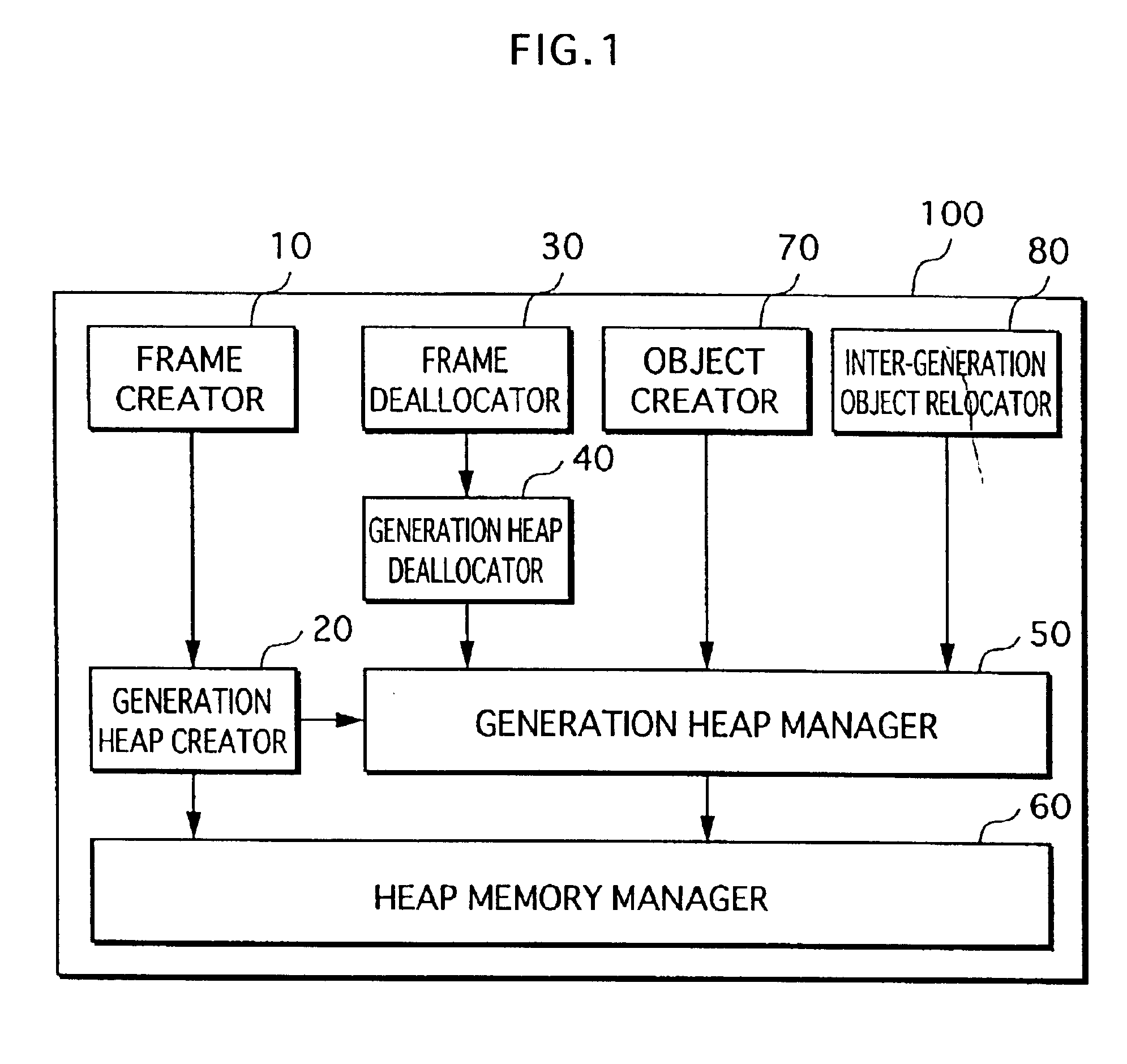
[0087]FIG. 1 is a block diagram schematically showing the construction of a garbage collector 100 according to an embodiment 1 of the present invention. The garbage collector 100 is implemented by a computer provided with a CPU, a memory, and other components by the CPU executing a control program stored in the memory. In addition, the garbage collector runs on an operating system, and thus...


PUM


Abstract

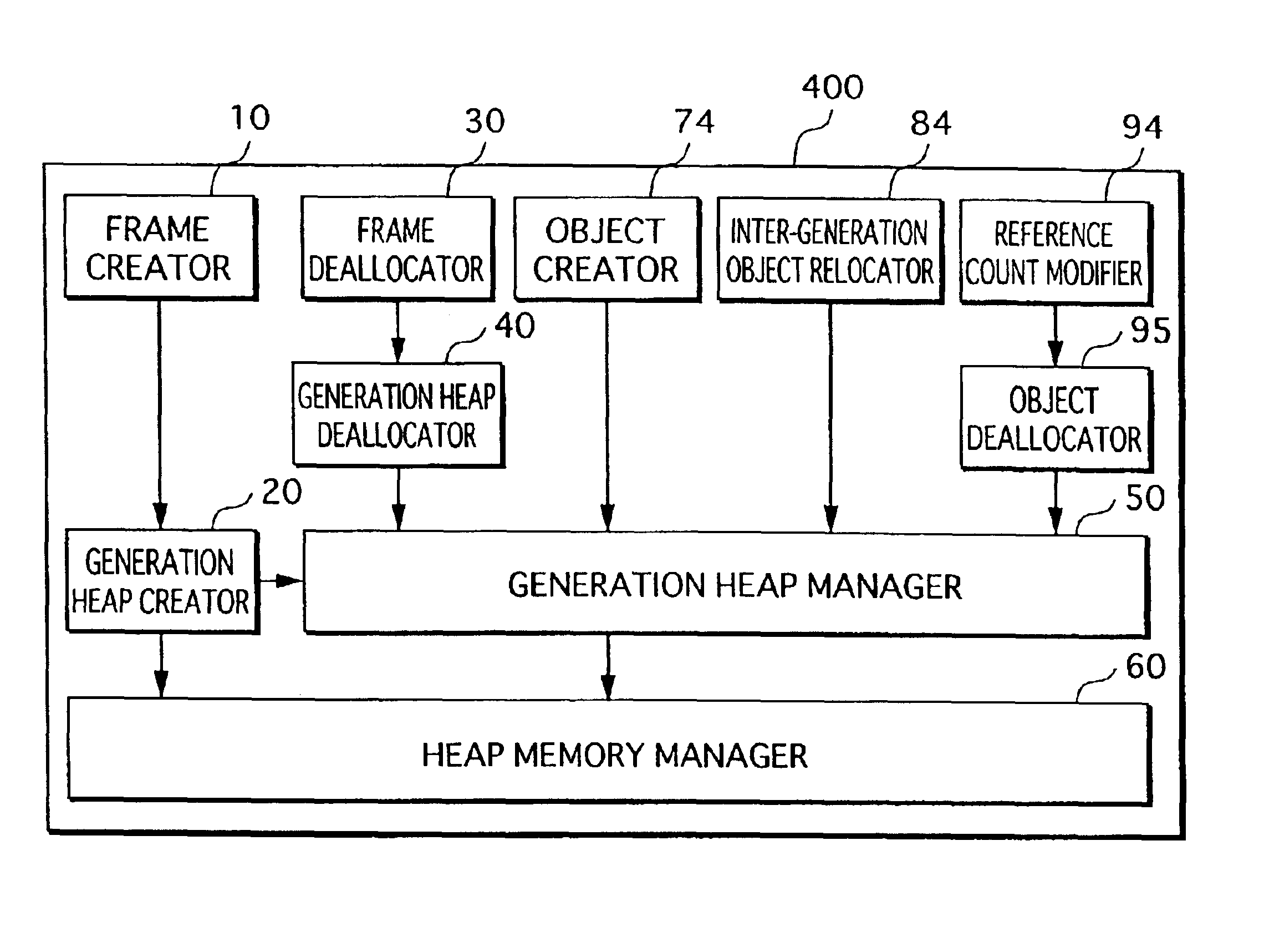
A garbage collector 100 is composed of a generation heap creator 20, an inter-generation object relocator 80, and a generation heap deallocator 40. The generation heap creator 20 creates a generation heap at a start of execution of a method. The inter-generation object relocator 80 relocates, upon detecting a reference from an object in an older generation heap to another object in a younger generation heap, the referenced object in the younger generation heap to the older generation heap. The generation heap deallocator 40 deallocates, at a completion of a method, a generation heap corresponding to the method.

Description

[0002]This application is based on an application No. 2001-382148 filed in Japan, the content of which is hereby incorporated by reference.BACKGROUND OF THE INVENTION[0003](1) Field of the Invention[0004]The present invention relates to techniques for implementing garbage collection that is suitably applied to real-time processing.[0005](2) Description of the Related Art[0006]Garbage collection is a type of operating system memory management. The garbage collection is implemented by a garbage collection algorithm to automatically free or deallocate a memory area that is no longer referenced by a program, so that an available memory area is increased. For example, Java™ (a registered trademark of Sun Microsystems, Inc., a cooperation of the United States) is provided with a garbage collector for implementing the algorithm.[0007]The garbage collector deallocates a dynamically allocated memory object (hereinafter, simply referred to as an “object”) to recycle if detecting that the obje...

Claims


Application Information

Patent Timeline
IPC IPC(8): G06F12/02G06F12/00G06F9/44G06F9/46
CPCG06F12/0269G06F12/0276Y10S707/99957
Inventor KAWAMOTO, TAKUJI
Owner PANASONIC CORP
Learn More