Replaceable demolition shear piercing tip

a technology of demolition and tip, applied in the direction of manufacturing tools, building repairs, portable power tools, etc., can solve the problem that the tip is not suitable for removal and replacement, and achieve the effect of preventing the upper jaw from being damaged

Inactive Publication Date: 2005-01-11
ANTARES CAPITAL AS AGENT
View PDF65 Cites 39 Cited by
  • Summary
  • Abstract
  • Description
  • Claims
  • Application Information

AI Technical Summary

Benefits of technology

Another object and advantage of the present invention is that the tip encapsulates the upper jaw and prevents the upper jaw from being

Problems solved by technology

The tip is not suitable for removal and replacement due to the high l

Method used


Image

  • Replaceable demolition shear piercing tip
  • Replaceable demolition shear piercing tip
  • Replaceable demolition shear piercing tip

Examples


Embodiment Construction

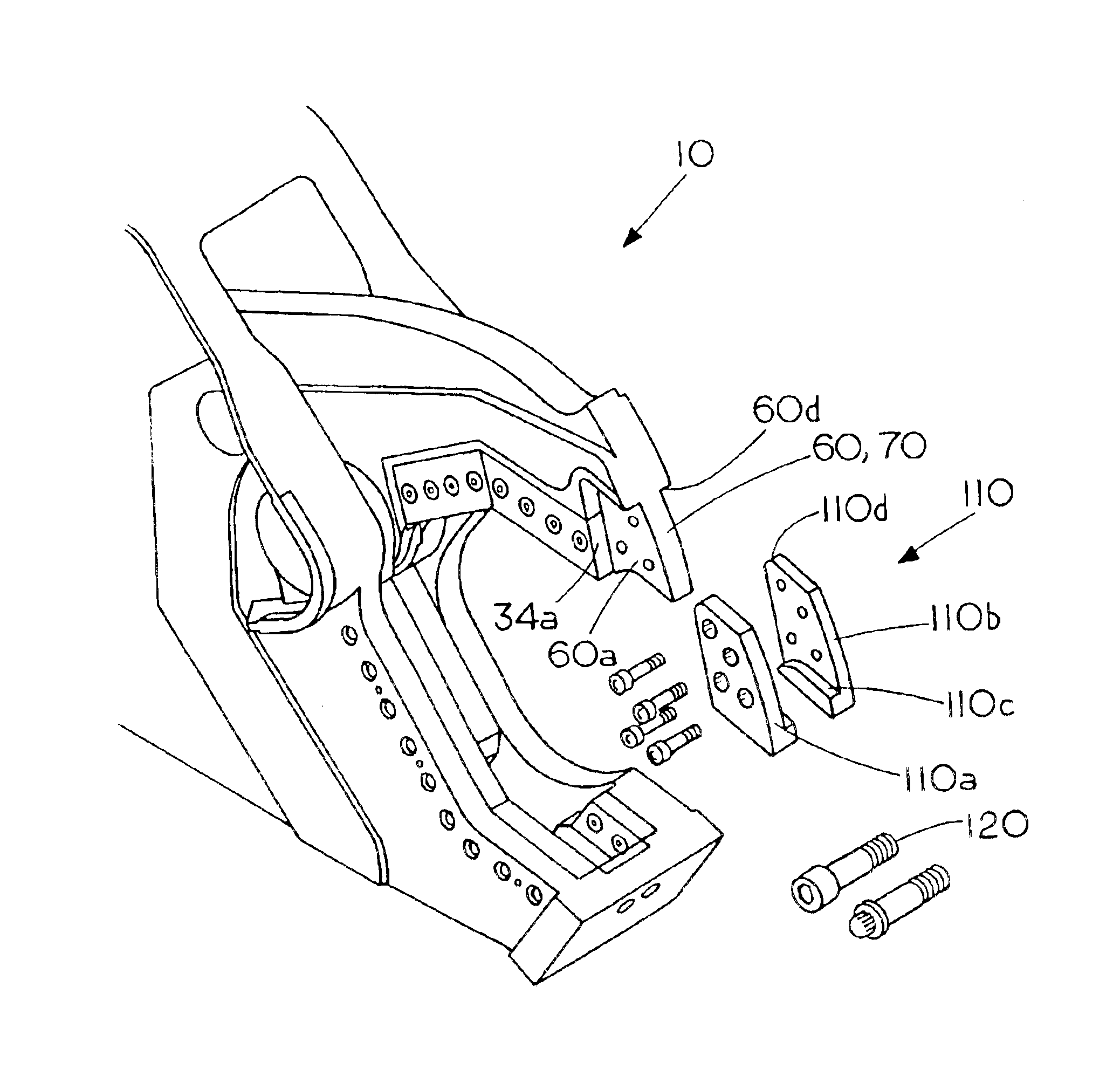
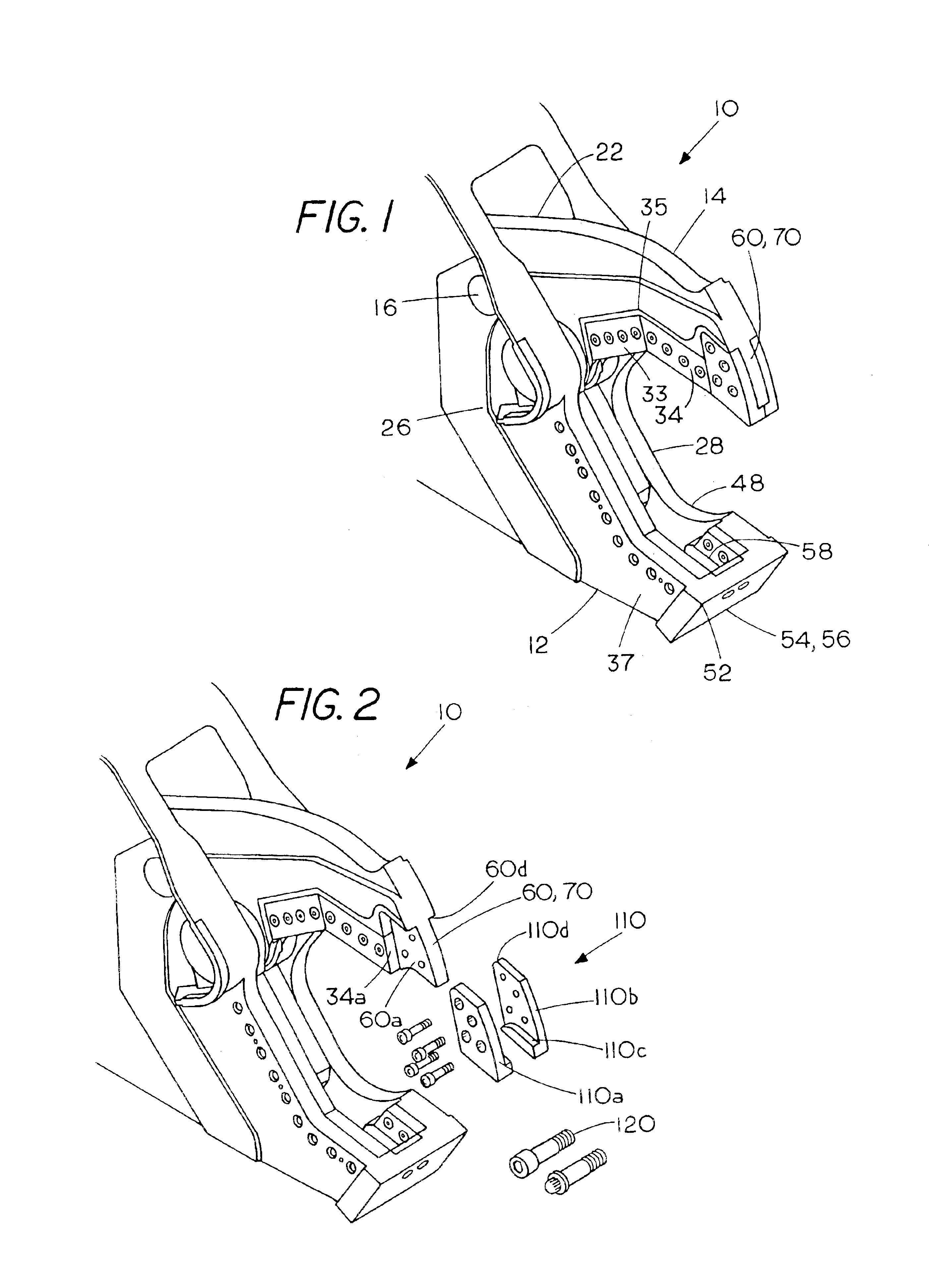
The heavy-duty demolition apparatus of the present invention is generally referred to in the Figures as reference numeral 10.

Referring to FIGS. 1 through 6, the heavy-duty demolition apparatus 10 comprises a lower jaw 12, an upper jaw 14, and pivot means 16 interconnecting the lower jaw 12 and upperjaw 14.

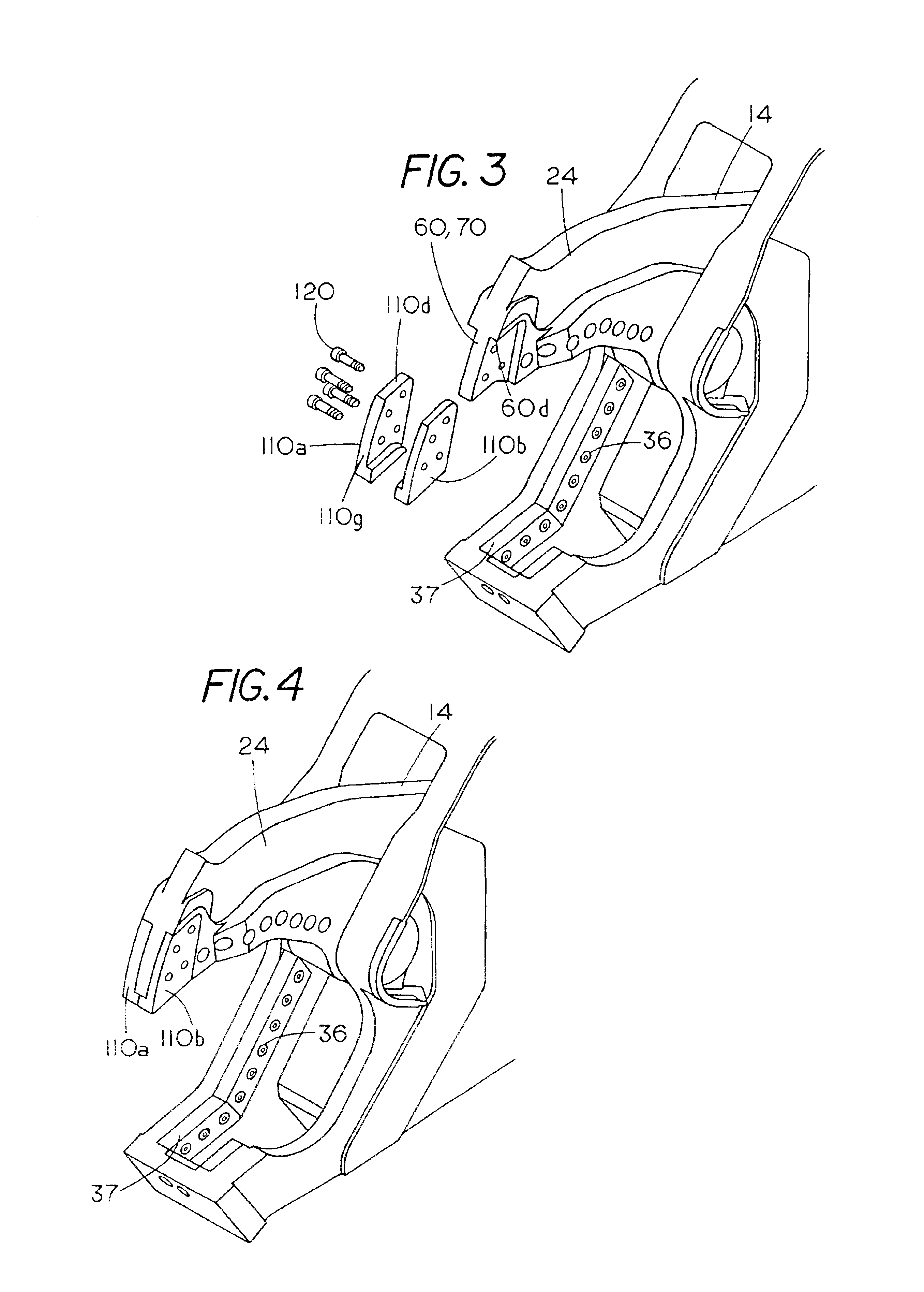
The upper jaw 14 has a first side 22, and a second side 24. The lower jaw 12 has a first mounting plate 26 adjacent the first side 22, and a second mounting plate 28 adjacent the second side 24. The first mounting plate 26 and second mounting plate 28 receive the pivot means 16 between them.

The upper jaw 14 has upper shear blades 33 and 34 meeting at apex 35 and the lower jaw 12 has lower shear blades 36 and 37 extending along each other for shearing a workpiece when the upper shear blades 33 and 34 are closed upon the lower shear blades 36 and 37. Preferably, the shear blades 33, 34, 36 and 37 are replaceable.

Preferably, the apparatus 10 further comprises a guide blade 48 on the l...


PUM

PropertyMeasurementUnit
Angleaaaaaaaaaa
Angleaaaaaaaaaa
Angleaaaaaaaaaa

Abstract

A heavy-duty demolition shear with a replaceable shearing tip has a lower jaw and an upper jaw piviotally connected to the lower jaw. The upper jaw has primary and secondary shear blades. A replaceable shearing tip is mounted to the upper jaw. The replaceable shearing tip has two L-shaped sections which engage the upper jaw between them. The replaceable shearing tip engages the upper jaw on at least three seats. The replaceable shearing tip is connected to the upper jaw by socket-head cap-screws.

Description

BACKGROUND OF THE INVENTIONA fuller understanding of the operation of the demolition apparatus of the present invention may be achieved by studying U.S. Pat. No. 4,519,135, hereby incorporated by reference. This invention relates to a heavy duty demolition apparatus, especially adapted to be mounted on a rigid boom of a mobile vehicle and particularly adapted to be mounted on the dipper stick of an excavator.The invention also has a replaceable shearing tip on the movable upper jaw.Heavy duty shears of the type that are powered by hydraulic cylinders are proving more and more useful in handling scrap and especially metal scrap of all sorts. Such scrap comes in many different forms, and may be in the form of pipes made of steel or soft iron or cast iron, ranging in sizes from 2 inches or smaller, and up to 8 or 10 inches in diameter or larger; structural beams such as I-beams, channels, angle beams in a large range of sizes, up to 8 or 10 inches across and larger; rods and heavy cabl...

Claims


Application Information

Patent Timeline
IPC IPC(8): B23D35/00B23D17/00E02F3/04E02F3/96
CPCB23D17/00E02F3/965B23D35/002B23D35/001E04G23/082
Inventor JACOBSON, DANIEL P.BACON, BRUCECHRISTENSON, ROSS D
Owner ANTARES CAPITAL AS AGENT
Why Eureka
Try Eureka