
Fuel tank venting system for reduced fuel permeation

a fuel tank and venting technology, which is applied in the direction of functional valve types, transportation and packaging, and other domestic objects, can solve the problems of fuel permeation of current fuel tank configurations, delamination of materials from each other, and undesirable effects

Inactive Publication Date: 2005-01-11
PLASTIC OMNIUM ADVANCED INNOVATION & RES SA
View PDF7 Cites 29 Cited by
  • Summary
  • Abstract
  • Description
  • Claims
  • Application Information

AI Technical Summary

Benefits of technology

The present invention is a fuel tank with a valve assembly for reducing fuel permeation through an outer lip. A retention member is attached to the outer lip to define an expansion boundary so that the outer lip only expands toward the venting valve to restrict hydrocarbon permeation therthrough. The fuel tank also includes a venting valve for venting gaseous hydrocarbon fluid at a predetermined pressure from the tank. The valve is disposed through the aperture to define a circumferential space between the inner side of the outer lip and the venting valve. The fuel tank further includes a cover attached to the outer layer to seal the valve between the cover and the outer layer. The invention also provides a venting assembly for venting gaseous fluid from a fuel tank. The technical effects of the invention are to reduce fuel permeation and to provide a sealed valve for venting gaseous fluid from the fuel tank.

Problems solved by technology

In many situations, this often results in delamination of the materials from each other.
Moreover, current fuel tank configurations may be prone to fuel permeation during use.
However relatively small, this too is undesirable.
In addition, the cost of such venting system is relatively high, since materials required to manufacture or purchase the permeation barrier hose is relatively expensive.
Such permeation barrier hose may comprise a significant portion relative to the entire cost of manufacturing the venting system.

Method used


Image

  • Fuel tank venting system for reduced fuel permeation
  • Fuel tank venting system for reduced fuel permeation
  • Fuel tank venting system for reduced fuel permeation

Examples


Embodiment Construction

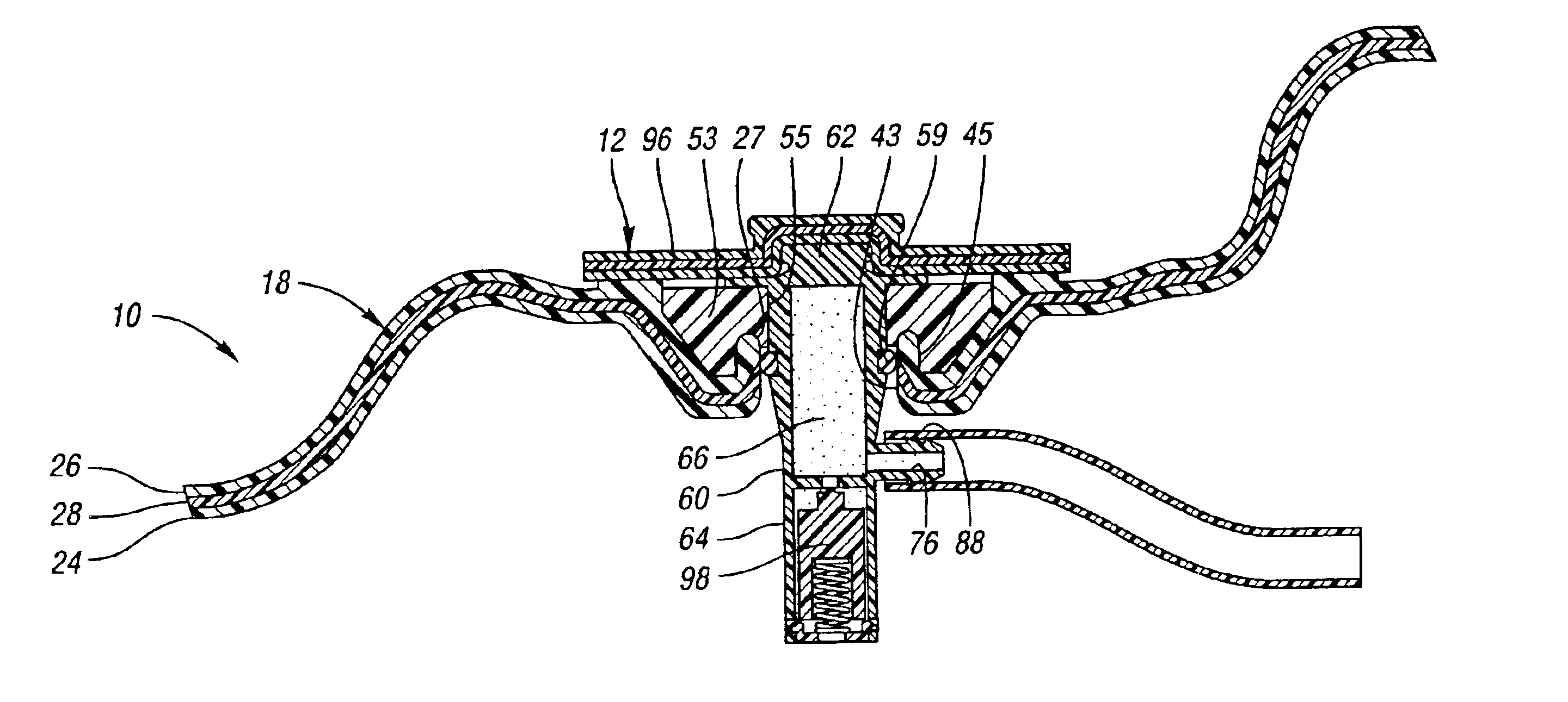
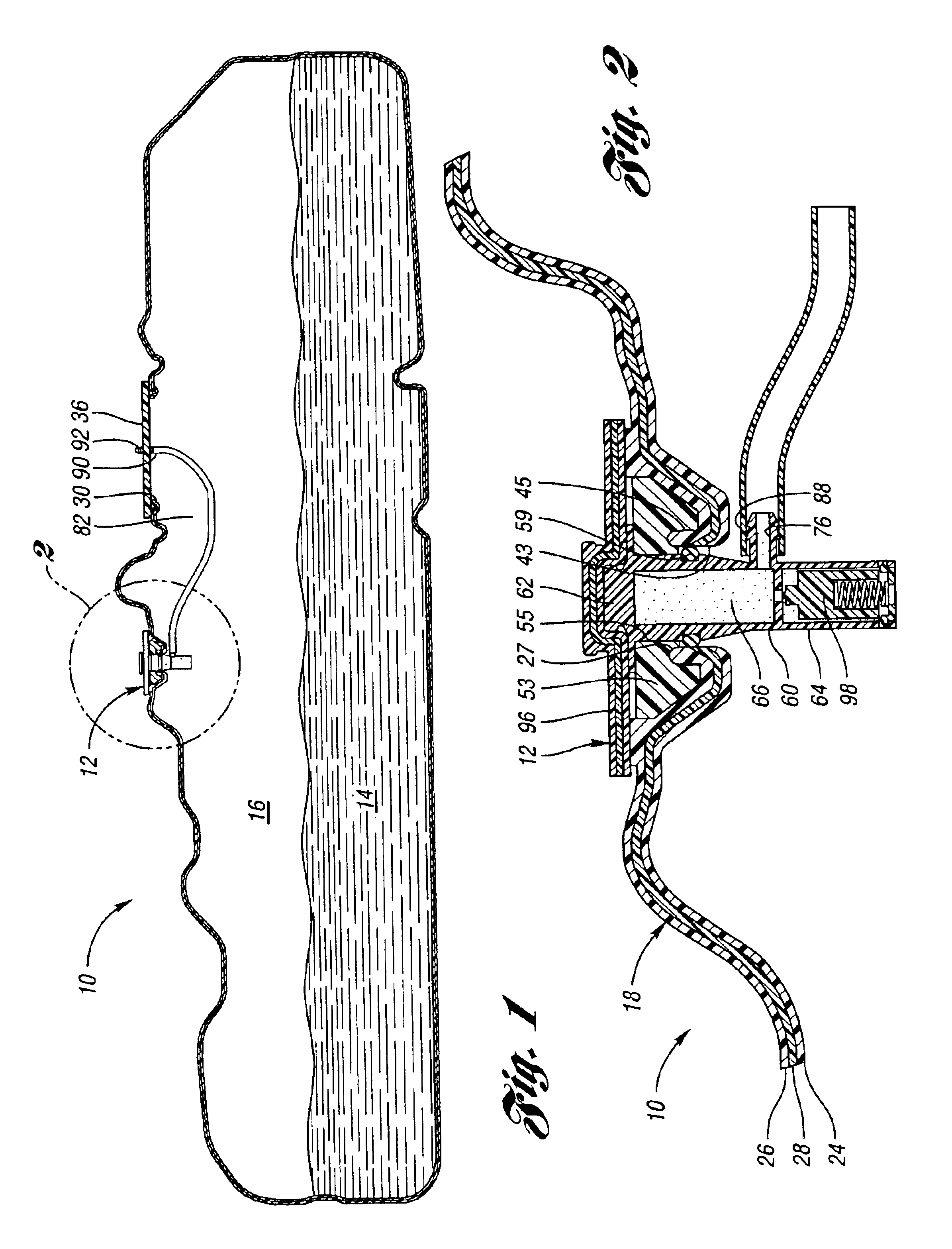
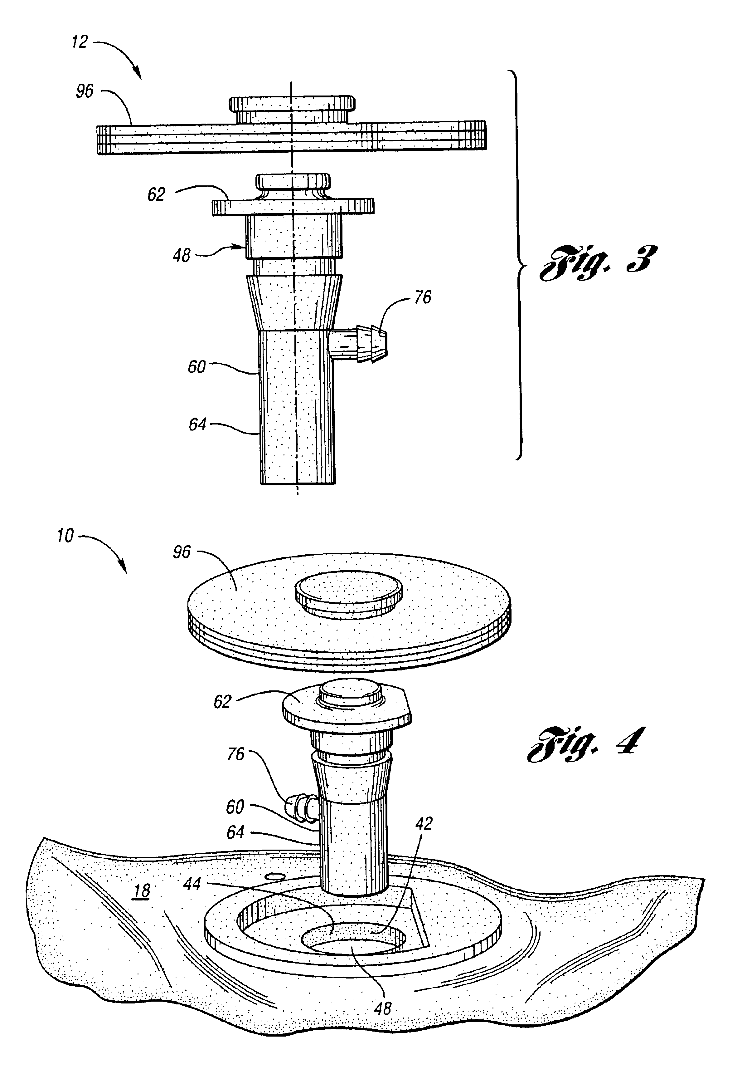
The present invention generally provides a venting system for venting a gaseous fluid from a fuel tank to reduce the risk of undesired exposure of gaseous hydrocarbon fluid to the atmosphere and eliminates a need of a costly permeation barrier hose typically used in vapor venting. The venting system generally provides a venting valve and a retention member disposed through an aperture formed through the fuel tank and sealed by welding a cover to the tank. The aperture of the tank is defined by an outer lip configured to receive the retention member such that the retention member serves as an immoveable boundary preventing the aperture from expanding. This allows compression of the outer lip and the venting valve thereby creating an enhanced seal to further reduce gaseous hydrocarbon fluids from escaping to the atmosphere.

FIG. 1 illustrates a fuel tank 10 having a venting system or assembly 12 for reduced fuel permeation from the tank 10. As shown, tank 10 includes venting assembly 1...


PUM

PropertyMeasurementUnit
pressureaaaaaaaaaa
fuel permeationaaaaaaaaaa
pressureaaaaaaaaaa

Abstract

The present invention involves a venting system for venting a gaseous fluid from a tank having an aperture and a fuel delivery module cover. The tank is made of a predetermined material. The venting system comprises a venting valve for venting gaseous hydrocarbon fluid at a predetermined pressure from the tank. The valve is disposed through the aperture to define a circumferential space between the inner side of the outer lip and the venting valve. The system further includes a cover comprising the predetermined material and attached to the outer layer to seal the valve between the cover and the outer layer. The system further includes a retention member disposed about the venting valve and attached to the outer layer about the outer side of the outer lip defining an expansion boundary so that the outer lip only expands toward the venting valve to seal the circumferential space when the tank absorbs hydrocarbons.

Description

BACKGROUND OF THE INVENTIONThe present invention relates to a fuel tank having a venting system for reduced fuel permeation.Blow-molded fuel tanks are known and have been widely used in industries such as the automotive industry. Vapor valving is a common way of venting a gaseous fluid at a particular pressure from a blow-molded fuel tank containing liquid and gaseous contents. In many venting systems of blow-molded fuel tanks, a gaseous fluid is vented through a typical venting valve which is disposed within a surface or tank shell of the tank of a vehicle. The gaseous fluid flows through a connection port of the valve, wherein the port is located outside the tank during operation of the valve. The connection port is in fluid communication with a permeation barrier hose through which the gaseous fluid flows to be received in a separate vapor canister within the vehicle for further processing.The above-mentioned system is adequate but can be improved. For instance, the venting valve...

Claims


Application Information

Patent Timeline
Patent Type & Authority Patents(United States)
IPC IPC(8): B60K15/035B60K15/03B65D90/34B65D90/22F16K24/04F16K24/00B29C65/00B29C65/02
CPCB29C65/02B29C66/73111B29C66/53246B60K15/03519B29K2023/065B29K2023/086B60K2015/03046B60K2015/03447B29L2031/7172B29C66/71Y10T137/3099Y10T137/86324B29C66/112B29C66/7234B29C66/131B29C66/24221B29K2077/00
Inventor BHAVSAR, DAVEN C.GINNARD, ROBERT J.KNAGGS, RICHARD A.
Owner PLASTIC OMNIUM ADVANCED INNOVATION & RES SA
Learn More