Air spring and pedestal

a technology of air spring and pedestal, which is applied in the direction of shock absorbers, mechanical equipment, transportation and packaging, etc., can solve the problems of air spring reinflating, damage to various rubber parts, and air cell collapse may become trapped between the piston and the upper mounting

Inactive Publication Date: 2005-01-11
MERITOR HEAVY VEHICLE SYST
View PDF14 Cites 32 Cited by
  • Summary
  • Abstract
  • Description
  • Claims
  • Application Information

AI Technical Summary

Benefits of technology

The air spring is not directly attached to the chassis but is mounted to contact a locating plate attached to the chassis. That is, the air spring is self-contained and moves as an enclosed unit relative to the chassis. Preferably, the locating plate includes a lip having a diameter greater than the diameter of the portion of the air spring to be received in the plate. The locating plate preferably has a generally frustro-conical configuration. The air cell is consistently laterally relocated by the locating plate. In addition, the locating plate self-aligns the air cell with the chassis to prevent the air cell from being trapped between the piston and upper mounting.
In one embodiment, the locating plate includes a protective skirt. The protective skirt further directs the air cell into a correct position with the locating plate. Further, by extending the protective skirt at the rear of the suspension system, the protective skirt protects the air spring from contact with material and debris.

Problems solved by technology

When a load is again placed on the suspension the air spring is compressed and the collapsed air cell may become trapped between the piston and upper mounting.
Damage to the various rubber parts, connections and mountings can then result when the air spring is reinflated.
These systems are only partially effective because the air spring extends faster than air can be drawn through inlet orifices or valving prevalently used.
However, this system creates realignment difficulties as the relatively small fittings can fail to properly relocate the air spring.
In addition, a partially inflated air cell is a further impediment to proper air spring realignment as the post is incorrectly positioned for contact with the cylindrical fitting.

Method used


Image

  • Air spring and pedestal
  • Air spring and pedestal
  • Air spring and pedestal

Examples


Embodiment Construction

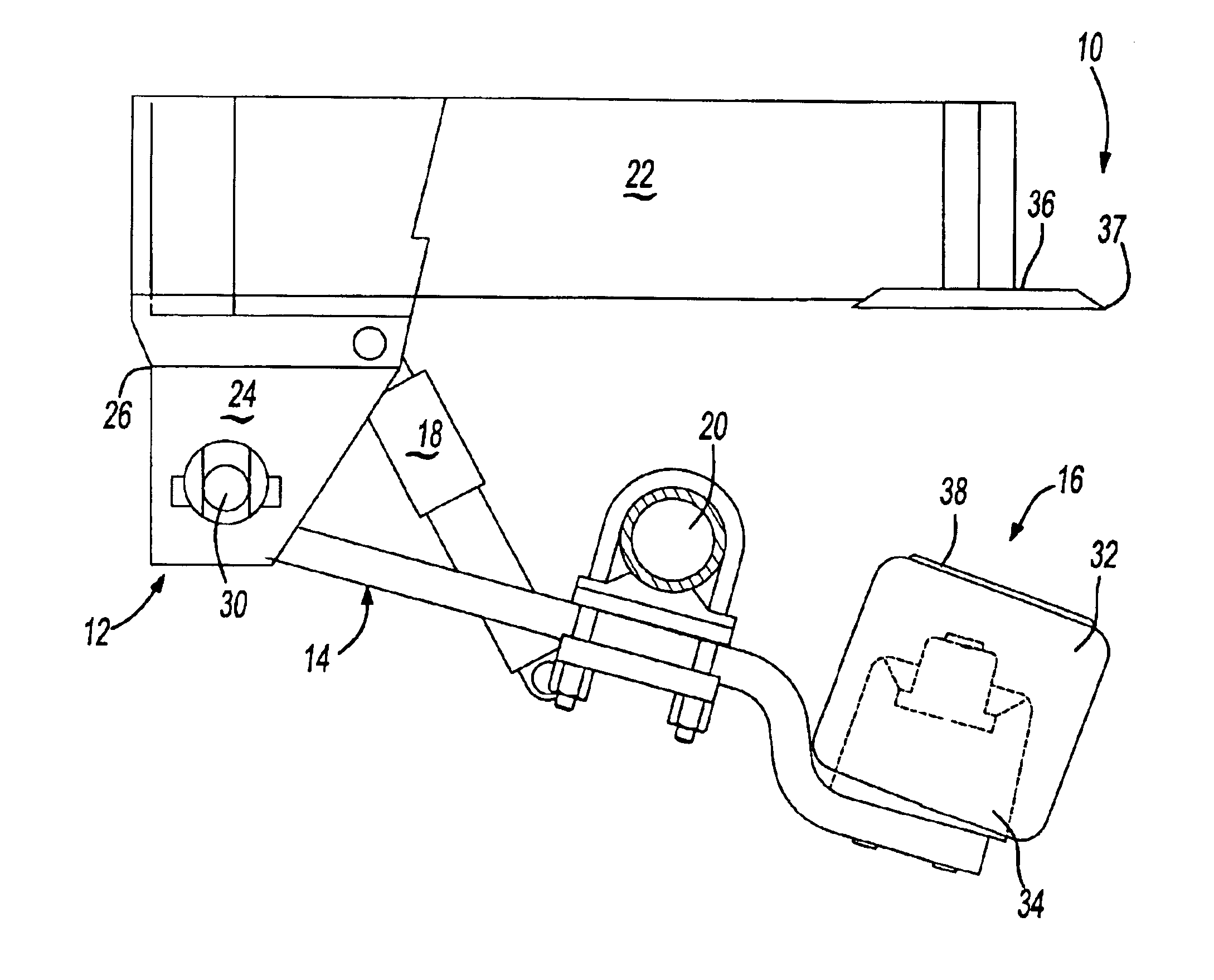
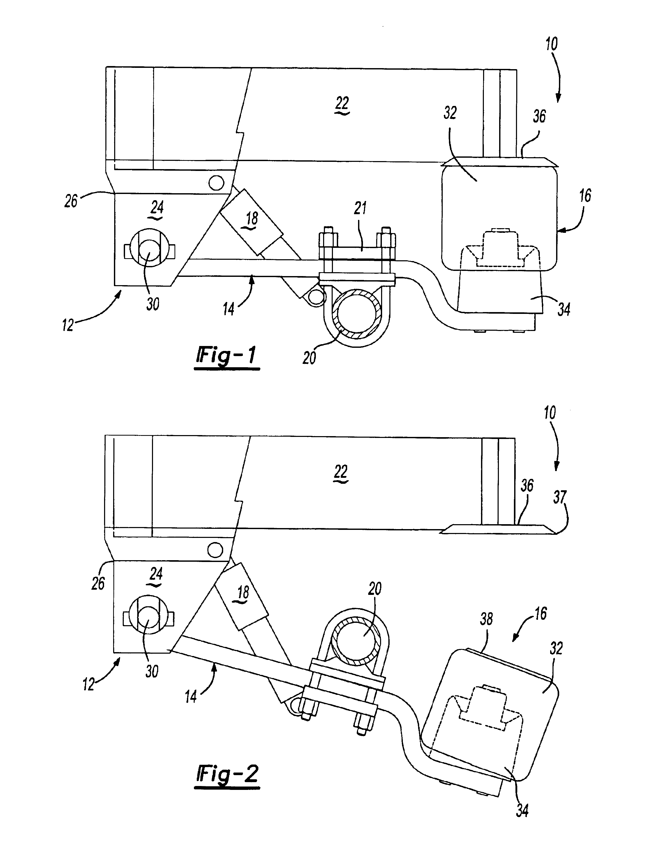
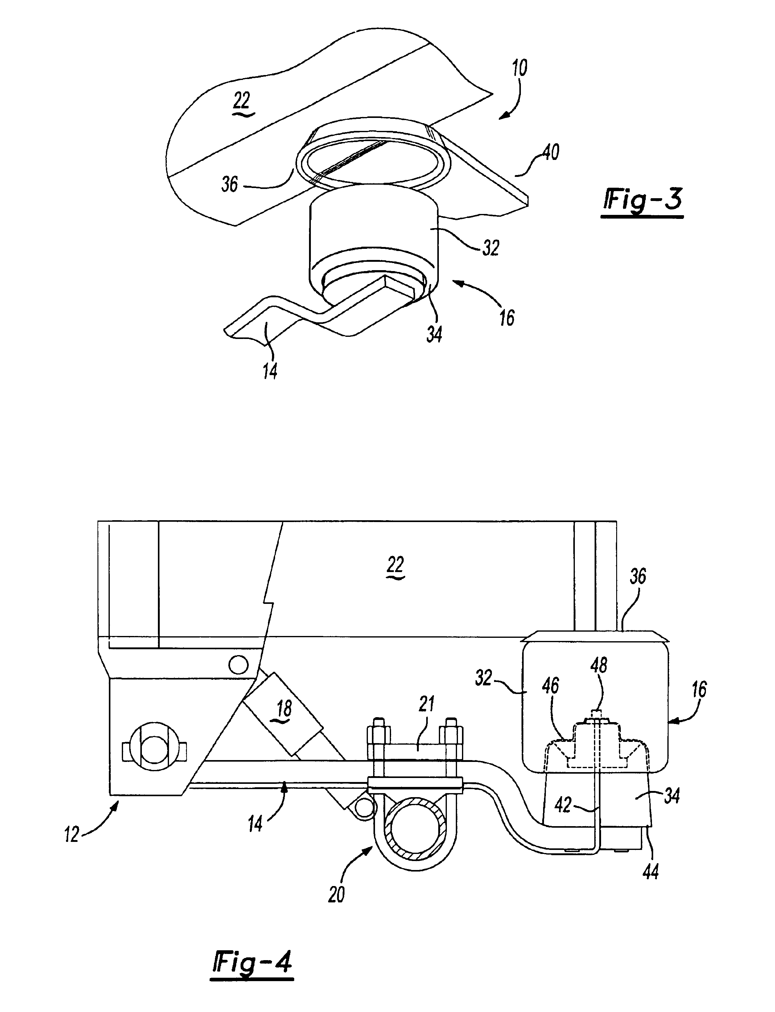
FIG. 1 illustrates an air suspension system 10 for a vehicle. The system 10 generally includes a bracket 12, a longitudinal member 14, an air spring 16, a damper 18 and an axle assembly 20. The system is fixed to a chassis of the vehicle (shown schematically at 22).

The disclosed bracket 12 has side members 24 which depend from the chassis, and a front plate 26 interconnecting the side members 24. The bracket 12 thus has a box-like construction, however, one skilled in the art will understand that other bracket configurations would benefit from the present invention.

The longitudinal member 14 extends generally lengthways of the vehicle and is pivotally connected within the bracket 12 to a pivot 30. The pivot 30 permits movement of the longitudinal member 14 and defines an axis generally transverse of the vehicle. From the pivot 30, the longitudinal member 14 extends rearwardly to mount the air spring 16. An axle assembly 20 of the vehicle is secured to the longitudinal member 14 betw...


PUM


Abstract

A suspension system includes a longitudinal member, an air spring, a damper and an axle assembly. The air spring is not directly attached to the chassis but is mounted to contact a locating plate attached to the chassis. The locating plate includes a lip such that the locating plate is of a frustum configuration that laterally locates and self aligns the air spring upon pivotal movement and re-alignment of the air spring with the chassis. Preferably, the suspension system includes a protective skirt which aids in bringing the air cell into a correct position with the locating plate. In addition the axle assembly extends away from the chassis at a speed restricted by the damper such that the anti-vacuum system can equalize the pressure within the air cell.

Description

BACKGROUND OF THE INVENTIONThe present invention relates to an air suspension, and more particularly to an anti-vacuum system with a separating air spring for a vehicle which requires an axle to be lowered away from the chassis.A common air suspension system typically comprises bracket secured to a chassis of a vehicle. A longitudinal member extending generally lengthwise of the vehicle is mounted to the bracket for pivoting about an axis generally transverse of the vehicle and to carry an axle having one or more road wheels. An air spring mounted spaced from the axis acts as an adjustable compression spring between the vehicle and the longitudinal member to bias the wheels for effective road engagement and to buffer axle and wheel vibration. The air spring typically includes a piston and an air cell. The piston is mounted to the longitudinal member and the air cell is attached to a bead plate mounted to the chassis.Vehicles fitted with an air suspension are sometimes used without b...

Claims


Application Information

Patent Timeline
Patent Type & Authority Patents(United States)
IPC IPC(8): B60G11/28B60G11/26B60G9/00
CPCB60G9/003B60G11/28B60G2200/31B60G2200/4622B60G2202/152B60G2202/412B60G2206/601B60G2204/128B60G2204/129B60G2204/201B60G2204/42B60G2204/4306B60G2204/44B60G2204/126
Inventor GRIFFITHS, PAUL J.
Owner MERITOR HEAVY VEHICLE SYST
Why Eureka
Try Eureka