Microcombustion heater having heating surface which emits radiant heat

a micro-combustion heater and heating surface technology, applied in the direction of combustion types, lighting and heating apparatus, furnaces, etc., can solve the problems of consuming expensive electrical energy which is converted into thermal energy, the flame cannot be transmitted through a narrow passage between solid walls, and the electric heater is generally difficult to realize stable combustion, etc., to achieve reliable combustion, high thermal efficiency, and the temperature of the gas is sufficiently low

Inactive Publication Date: 2005-01-11
MARUTA KAORU +1
View PDF7 Cites 15 Cited by
  • Summary
  • Abstract
  • Description
  • Claims
  • Application Information

AI Technical Summary

Benefits of technology

According to the above structure, the direction of the flow of the premixed gas and the direction of the flow of the combustion gas are opposite to each other, so that sufficient heat exchange is performed between the opposite flows. Therefore, the premixed gas which is drawn into the combustion chamber 8 is sufficiently preheated, and reliable combustion can be performed. In addition, when the combustion gas is discharged, the temperature of the gas is sufficiently low; thus, thermal loss caused by the discharge of the combustion gas is small. Therefore, the microcombustion heater has a high thermal efficiency and a superior combustion stability while the device is small.
Furthermore, the width of the premixed gas passage is the quenching distance or less. Therefore, the flame does not flow backward through the premixed gas passage and thus safety is high.
In addition, one of the faces of the microcombustor, between which the spiral passages are formed, is a heating surface which emits radiant heat. Therefore, a target object can be effectively heated by the radiant heat while the temperature distribution of the target object is accurately controlled. Accordingly, the microcombustion heater has a high thermal efficiency while the device is small, and the performance of the microcombustion heater is stable; thus, the microcombustion heater can be used as a substitute for the electric heater.

Problems solved by technology

If such small heaters are of a combustion type (i.e., combustion heaters), it is generally difficult to realize stable combustion.
However, the free radicals are deactivated when they collide against a solid wall; thus, the flame cannot be transmitted through a narrow passage between solid walls.
As explained above, small heaters which are generally used for heating semiconductors are electric heaters, and the electric heater consumes expensive electrical energy which is converted into thermal energy.
Therefore, this type of heater is not economical.

Method used


Image

  • Microcombustion heater having heating surface which emits radiant heat
  • Microcombustion heater having heating surface which emits radiant heat
  • Microcombustion heater having heating surface which emits radiant heat

Examples


Embodiment Construction

Hereinafter, an embodiment according to the present invention will be explained with reference to the drawings.

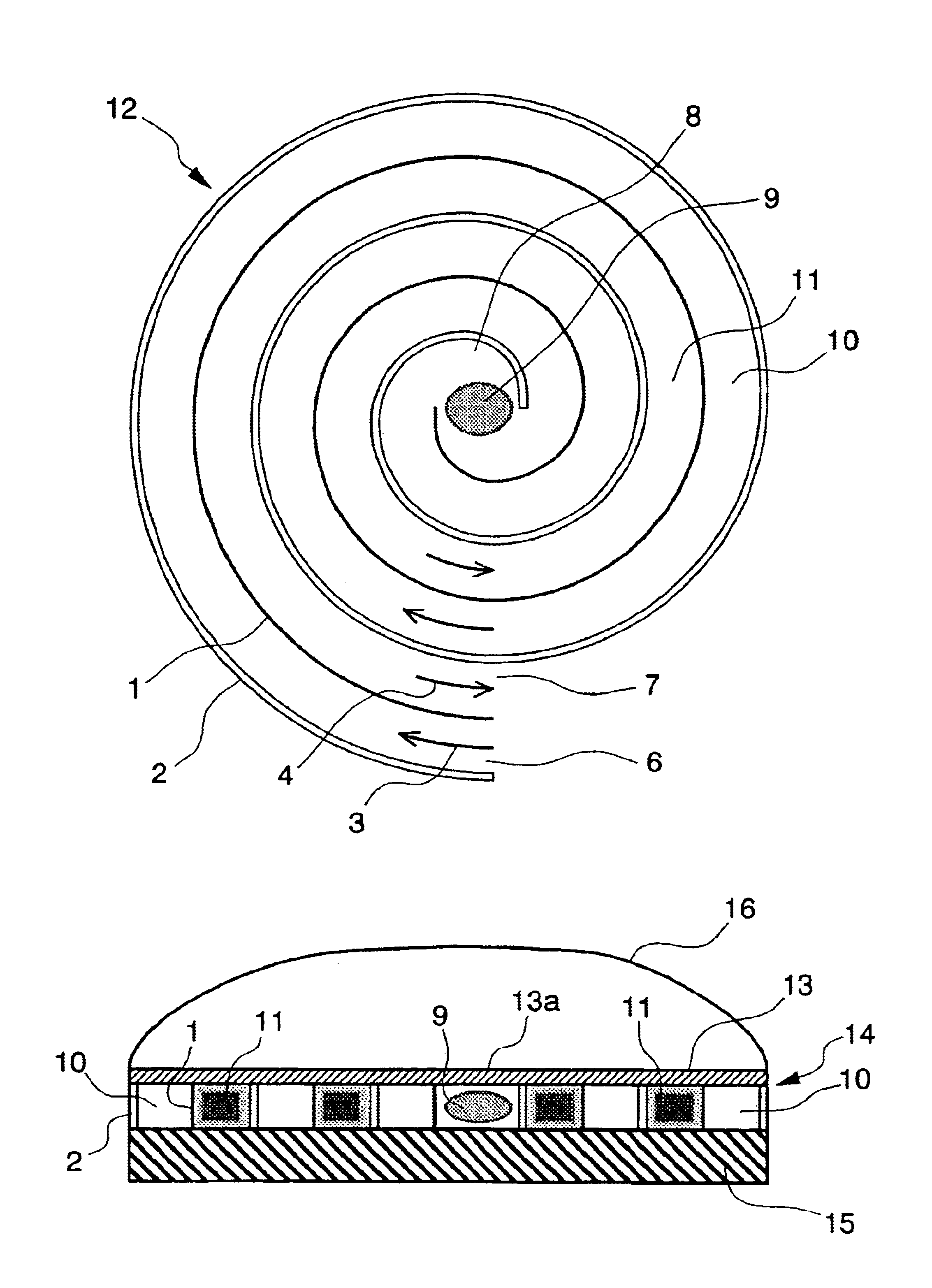
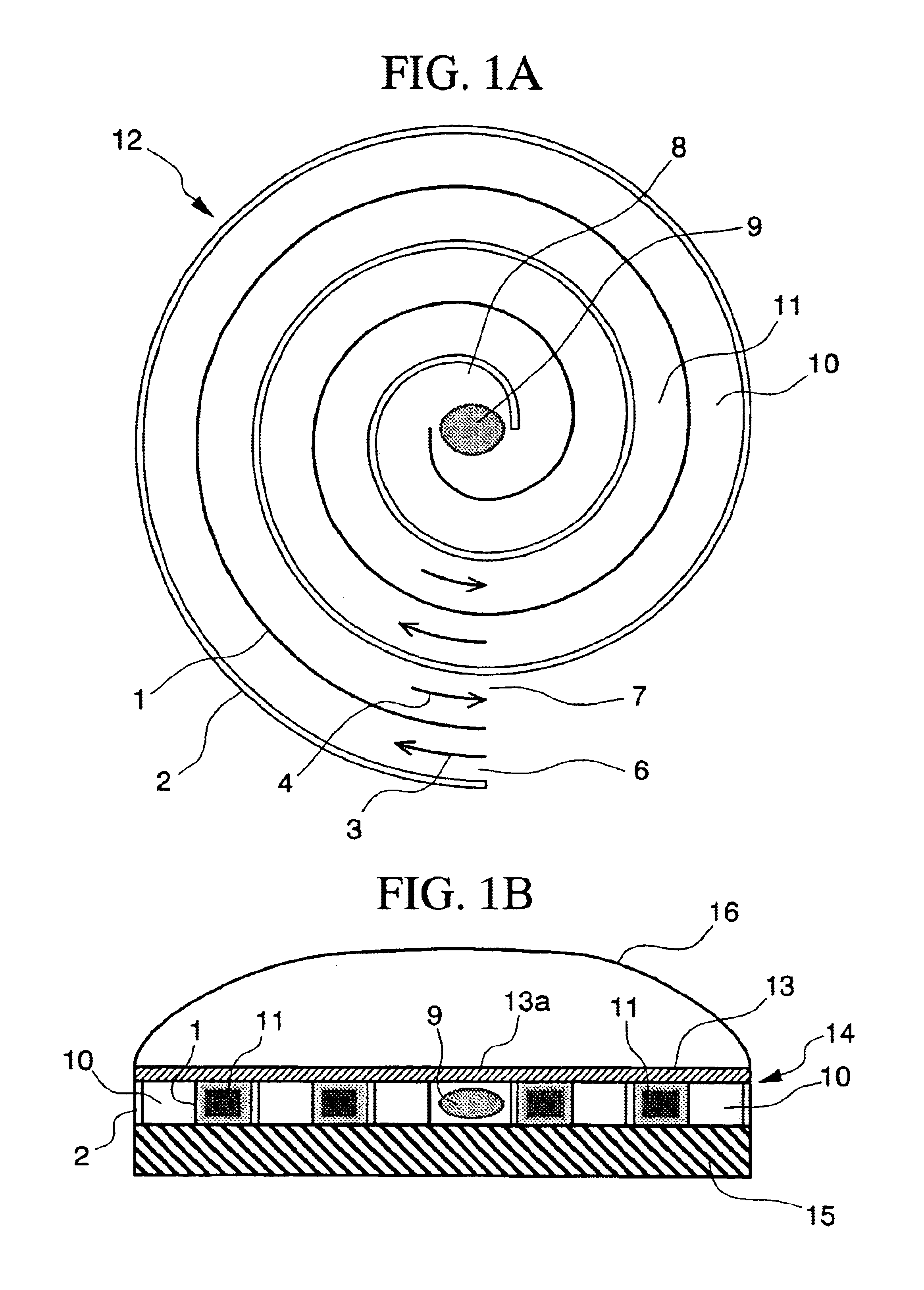
FIGS. 1A and 1B are diagrams for showing the structure of a microcombustion heater as an embodiment of the present invention. FIG. 1A is a sectional view in a plane direction parallel to the heating surface (explained below), and FIG. 1B is a cross-sectional view along a center line. In these figures, parts corresponding to those in the above-explained FIGS. 5A and 5B are given identical reference numerals, and duplicate explanations are simplified or omitted.

In FIGS. 1A and 1B, reference numeral indicates a heating wall, and reference numeral 2 indicates a heat insulating wall.

As shown in the figures, the passage 10 for a premixed gas of the air and a combustion gas, which is drawn into the combustion chamber 8, and the passage 11 for a combustion gas which is drawn from the combustion chamber 8, are formed in a manner such that the heating wall 1 is placed between the pas...


PUM


Abstract

A small microcombustion heater which can realize reliable combustion. The heater has a premixed gas passage which reaches a combustion chamber, and a passage for a combustion gas drawn from the combustion chamber. The passages are arranged in a spiral form in a manner such that a heating wall is provided between the passages. The width of the premixed gas passage is a quenching distance or less, where the quenching distance is determined depending on the premixed gas. The heater has two outer faces for holding the spiral passages from both sides of the upper and lower edges of the heating wall, and at least one of the outer faces is a heating surface for emitting radiant heat. Typically, the spiral passages are placed between a heat-resisting heating plate and a heat insulating plate, and an outer face of the heat-resisting heating plate functions as the heating surface.

Description

BACKGROUND OF THE INVENTION1. Field of the InventionThe present invention relates to a microcombustion heater having a diameter of 1 to a few centimeters.2. Description of the Related ArtIn a process for heating an object contained in a glass tube so as to produce a semiconductor or the like, the glass tube may be surrounded by several small heaters so as to form a suitable panel heater, and the heating rate of each small heater is controlled in order to control the temperature distribution of the object to be heated.If such small heaters are of a combustion type (i.e., combustion heaters), it is generally difficult to realize stable combustion. Therefore, small electric heaters are used for manufacturing semiconductors.On the other hand, small combustors called Swiss-roll combustors are known, which will be explained below.FIG. 5A is a diagram showing the structure of a one-dimensional counterflow combustion heat exchanger. In the figure, reference numeral 1 indicates a heating wal...

Claims


Application Information

Patent Timeline
Patent Type & Authority Patents(United States)
IPC IPC(8): F23D14/46F23D14/66F23D14/62F23D14/12F23D14/02F23D14/00
CPCF23D14/125F23D14/66F23D14/62Y02E20/34F23D14/00
Inventor MARUTA, KAORUFUJIMORI, TOSHIRO
Owner MARUTA KAORU
Why Eureka
Try Eureka