
Method for the impact or shot evaluation in a shooting range and shooting range

a technology for impact or shot evaluation and shooting range, which is applied in the field of impact or shot evaluation in shooting range and shooting range, can solve the problem of even shorter stop time and achieve the effect of reducing evaluation time and great accuracy

Inactive Publication Date: 2005-01-11
DYNAMIT NOBEL AG
View PDF16 Cites 17 Cited by
  • Summary
  • Abstract
  • Description
  • Claims
  • Application Information

AI Technical Summary

Benefits of technology

Therefore the object underlying the invention is to indicate a method and firing range for electronic hit or shot evaluation of shots fired in a firing range for recreational shooting and hunt training, in which the target to be shot at is projected onto a target wall as target output via a light source movable in all directions and, for hit evaluation, an infrared camera produces a shot image on the target wall, with which both great accuracy is achieved and evaluation time is reduced to such an extent that the marksman can fire two shots in succession without detriment.
One advantage of this process and the firing range, inter alia, is that because of the lack of coincidence of the two photographs, before and after the shot, the mechanics can be far simpler. A small amount of overshooting at the time of taking the photograph can even be tolerated. This also makes the stopping time even shorter. Additionally a saving of time results because the amount of data to be processed is smaller.
In a preferred embodiment, the infrared camera is arranged on a vertically and horizontally adjustable turntable, the movement of which is controlled by the control device as a function of the target coordinates. As, after the shot has been fired, a short time elapses until the shot hits the target wall, the movement of the turntable can be controlled in such a way that it takes this into account. Advantageously a certain lead is set.
Evaluation with a panning infrared line camera is a further embodiment. This camera is arranged in such a way that the line elements photograph a perpendicular line of the wall from top to bottom. After a small rotational movement which is aligned to the pulses per angle, one column is read in at a time by a pulse generator arranged on the horizontal axis. The reading in of a line / column lasts only microseconds. One column is therein written into the memory in one operation. The area is re-composed in the memory. The advantage of this arrangement is that the resolution is dependent only on the number of pulses per angle. It is therefore possible to achieve higher resolutions than with area cameras. Neither is the camera stopped to photograph a column, but goes on moving. Additionally the second rotational axis of the mirror is dispensed with. The range in which the marksman can miss, and yet a correct evaluation is possible, can therefore be greater because any number of columns can be read out. The only limitation is the computer's memory. Moreover, the evaluation time becomes longer.

Problems solved by technology

This also makes the stopping time even shorter.

Method used


Image

  • Method for the impact or shot evaluation in a shooting range and shooting range
  • Method for the impact or shot evaluation in a shooting range and shooting range

Examples


Embodiment Construction

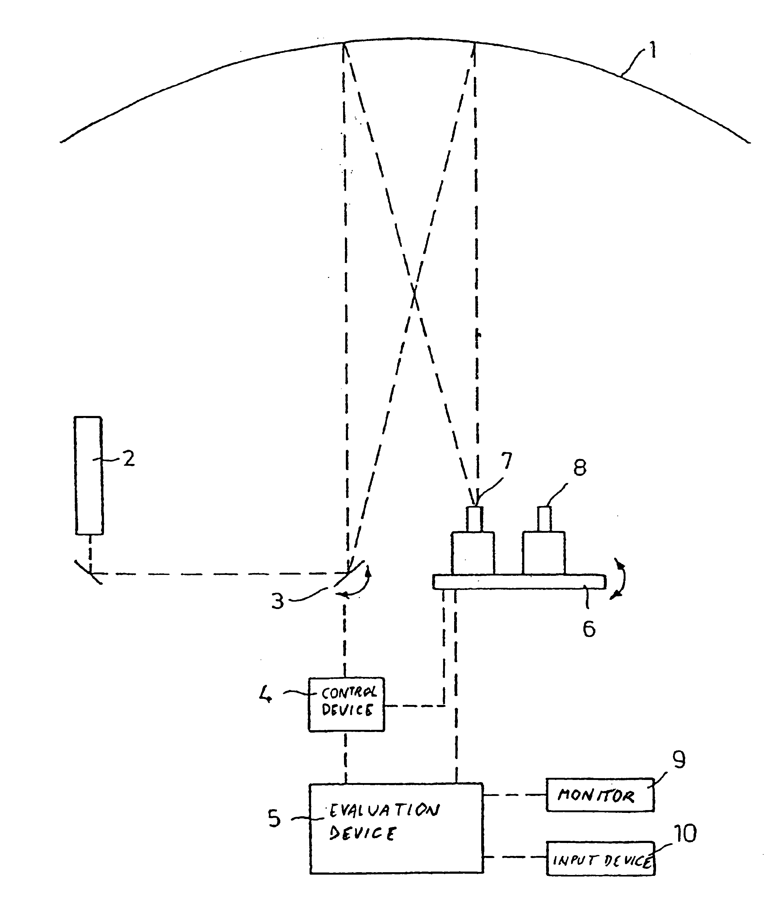
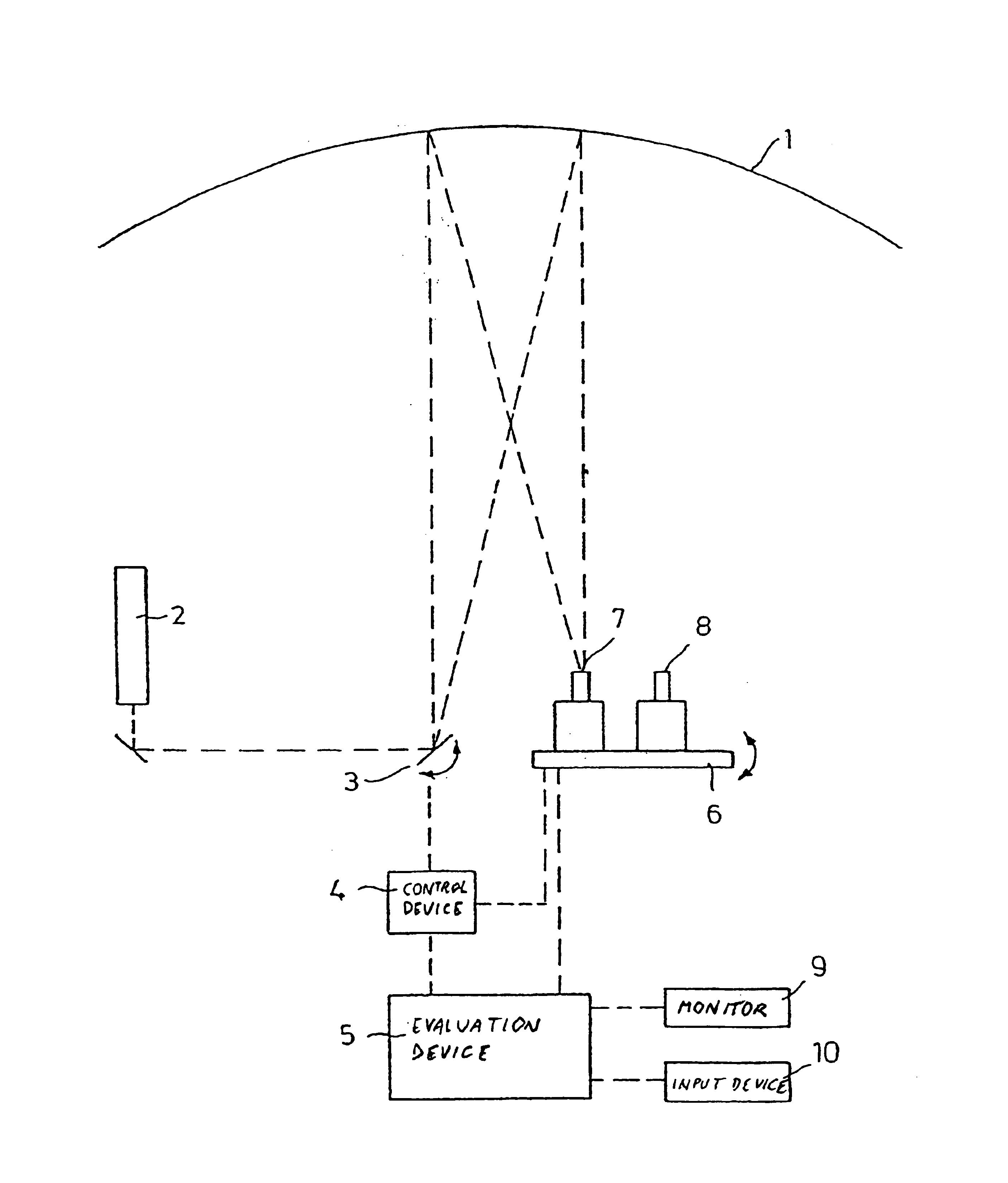
This FIGURE shows a target wall 1 of an approximate length of 42 m. The height is 3.50 m. In front of the target wall 1 is mounted an arrangement for the method of the invention, which arrangement is illustrated here only by way of example and schematically. The reference numeral 2 designates a laser.

The laser beam generated therein is directed via a movable mirror 3 on to the target wall 1 and there generates the target image, e.g. a running hare or a flying pigeon. An infrared camera 7 and a video camera 8 are arranged on a horizontally and vertically movable turntable 6.

The target coordinates are stored in a control device 4 in the form of a chronological sequence. The control device 4 then controls the mirror 3 and the turntable 6 and, during controlling, forwards the target coordinates to an evaluation device 5. The signals from the infrared camera 7 also arrive in this evaluation device 5. Since the coordinates of the target image are known, the coordinates of the image of the...


PUM


Abstract

The invention relates to a method for evaluating electronic impacts or shots of fired shots in a shooting range for sportsmen and for hunter training. The target to be shot at is provided as a light spot and is projected onto a target wall (1) via a light source in such a way that said target can move in all directions. An infrared camera (7) records the shooting image on the target wall (1) for evaluating the impact. The aim of the invention is to increase accuracy and reduce the evaluation time. Target co-ordinates arm detected while the target is being provided. Said target coordinates arm compared to the impact co-ordinates obtained by means of the impact evaluation. An impact is signalled when an impact falls short of a given divergence.

Description

BACKGROUND OF THE INVENTIONThe invention relates to a method for electronic hit or shot evaluation of shots fired in a firing range for recreational shooting and hunt training, in which the target to be shot at is projected, on to a target wall as target output, via a light source as a bright spot movable in all directions and, for evaluating hits, an infrared camera produces a record of the shot image on the target wall, and relates to a firing range.A method of this kind and firing range, is known from DE 37 29 613 C2. With this, the target wall is photographed by an infrared camera and, before the shot is fired, its image is written as a digital signal into the memory of a computer, in which it is available as a gray scale value, arranged in lines and columns. The coordinates of the light spot appearing on the target wall, as well as the image generated of the shot-at target wall after the shot has been fired, are stored in the computer and the gray scale values of the two images...

Claims


Application Information

Patent Timeline
IPC IPC(8): F41J5/00F41J5/02F41J9/00F41J5/08F41J9/14F41G3/26F41G3/00A63F9/02F41J5/10F41J1/00F41J11/00
CPCF41G3/2694F41J9/14F41J5/08F41J5/02
Inventor PURA, RUDOLF
Owner DYNAMIT NOBEL AG
Learn More